| ACCESSORIES | |
|
|
|
| Connect the lug on the electrode cables from the | |
| power source to the tab on the contact nozzle | |
| and tighten the bolt and nut. See Figure C.1. |
|
| Operation - DO NOT completely straighten the | |
electrode. A slight curvature is required in the electrode to insure good electrical contact inside the contact tip.- Replace the contact tip when it noMaintenancelonger provides accurate wire location or good electrical contact. Rusty and dirty wire or exces- sively high currents increase tip wear. Always keep replacement tips in stock.
To replace the contact tip, first loosen the retain- ing wing nut and remove the flux cone body. Then unscrew the tip and replace it.
A special socket head screw holds the nozzle body to the insulator. If the nozzle body becomes loose, remove the nozzle from the head, tighten the screw and reassemble nozzle.
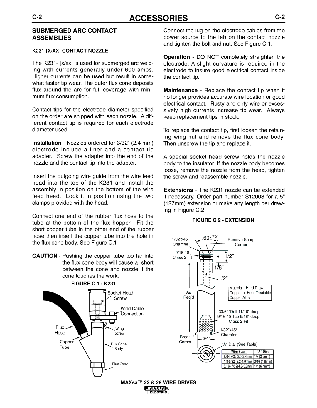
- The K231 nozzle can be extended ifExtnecessarynsions. Order part number S12003 for a 5” (127mm) extension or make any length per draw- ing in Figure C.2.
FIGURE C.2 - EXTENSION
| Socket Head | |
| Screw | |
| Weld Cable | |
| Connection | |
Flux | Wing | |
Hose | Screw | |
Copper | Flux Cone | |
Tube | ||
Body | ||
| Flux Cone |
1/32”x45° | 60° + 2° |
| Remove Sharp | |||||||||||||||||||||||
Chamfer |
|
|
|
|
|
|
|
|
|
|
|
|
|
| Corner |
|
|
|
| |||||||
|
|
|
|
|
|
|
|
|
|
|
|
|
|
|
|
|
|
|
|
|
|
|
| |||
|
|
|
|
|
|
|
|
|
|
|
|
|
| 1/2” |
|
|
|
| ||||||||
Class 2 Fit |
|
|
|
|
|
|
|
|
|
|
|
|
|
|
|
| ||||||||||
|
|
|
|
|
|
|
|
|
|
|
|
|
|
| ||||||||||||
|
|
|
|
|
|
|
|
|
|
|
|
|
|
|
|
|
|
|
|
|
|
|
|
|
| |
|
|
|
|
|
|
|
|
|
|
|
|
|
|
| 1/8” |
|
|
|
| |||||||
|
|
|
|
|
|
|
|
|
|
|
|
|
|
|
|
| 1/2” |
|
|
|
| |||||
|
|
|
|
|
|
|
|
|
|
|
|
|
|
|
|
|
|
|
|
| ||||||
|
|
|
|
|
|
|
|
|
|
|
|
|
|
|
|
|
|
|
|
|
|
|
|
|
| |
|
| As |
|
|
|
|
|
|
|
|
|
|
|
|
|
|
|
| Material - Hard Drawn |
| ||||||
|
|
|
|
|
|
|
|
|
|
|
|
|
|
|
|
|
| Copper or Heat Treatable |
| |||||||
|
|
|
|
|
|
|
|
|
|
|
|
| ||||||||||||||
| Req’d |
|
|
|
|
|
|
|
|
|
|
|
|
|
|
|
| Copper Alloy |
|
|
|
| ||||
|
|
|
|
|
|
|
|
|
|
|
|
|
|
|
|
|
|
|
|
| ||||||
|
|
|
|
|
|
|
|
|
|
|
|
|
|
|
|
| 33/64”Drill 11/16” deep | |||||||||
|
|
|
|
|
|
|
|
|
|
|
|
|
|
|
| |||||||||||
|
|
|
|
|
|
|
|
|
|
|
|
|
|
|
|
|
|
|
|
|
| Class 2 Fit |
|
|
|
|
|
|
|
|
|
|
|
|
|
|
|
|
|
|
|
|
|
|
| 1/32”x45° |
|
|
|
| |||
|
|
|
|
|
|
|
|
|
|
|
|
|
|
|
|
|
|
|
|
|
|
| ||||
Break |
|
|
| 3/4” |
|
|
|
|
|
| Chamfer |
|
|
|
| |||||||||||
|
|
|
|
|
|
|
|
|
|
|
|
| ||||||||||||||
|
|
|
|
|
|
|
|
|
|
|
|
|
|
|
|
| ||||||||||
Corner |
|
|
|
|
|
|
|
|
|
| “A” Dia. (See Table) | |||||||||||||||
|
|
|
|
|
|
|
|
|
|
|
|
| ||||||||||||||
|
|
|
|
|
|
|
|
|
|
|
|
|
|
|
|
|
|
|
| |||||||
|
|
|
|
|
|
|
|
|
|
|
|
|
|
|
|
|
|
|
|
|
| Wire Size |
| “A” Dim. |
| |
|
|
|
|
|
|
|
|
|
|
|
|
|
|
|
|
|
|
|
|
|
|
|
| |||
|
|
|
|
|
|
|
|
|
|
|
|
|
|
|
|
|
|
|
|
|
|
|
| |||
|
|
|
|
|
|
|
|
|
|
|
|
|
|
|
|
|
|
|
|
| 1/8 (3.2mm) |
| ||||
|
|
|
|
|
|
|
|
|
|
|
|
|
|
|
|
|
|
|
|
| 3/16 (4.8mm) |
| ||||
|
|
|
|
|
|
|
|
|
|
|
|
|
|
|
|
|
|
|
| 3/16 |
| 1/4 (6.4mm) |
| |||