OPERATION | ||
|
|
|
The function of the covered electrode is much more than simply to carry current to the arc. The electrode is composed of a core metal wire around which has been extruded and baked a chemical covering. The core wire melts into the arc and tiny droplets of molten metal shoot across the arc into the molten pool. The electrode provides additional filler metal for the joint to fill the groove or gap between the two pieces of the base metal. The covering also melts or burns in the arc. It has several functions. It makes the arc steadier, provides a shield of
1.The type of deposit you want, e.g., mild steel, stainless, low alloy, hardfacing.
2.The thickness of the plate you want to weld.
3.The position it must be welded in (downhand,
4.The surface condition of the metal to be welded.
5.Your ability to handle and obtain the desired electrode.
Four simple manipulations are of prime importance. Without complete mastery of these four, further attempts at welding are futile. With complete mastery of the four, welding will be easy.
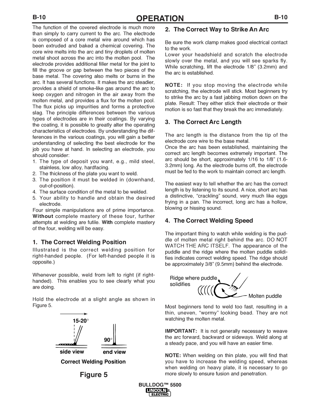
1. The Correct Welding Position
Illustrated is the correct welding position for
Whenever possible, weld from left to right (if right- handed). This enables you to see clearly what you are doing.
Hold the electrode at a slight angle as shown in Figure 5.
90°
side view | end view |
Correct Welding Position
Figure 5
2. The Correct Way to Strike An Arc
Be sure the work clamp makes good electrical contact to the work.
Lower your headshield and scratch the electrode slowly over the metal, and you will see sparks fly. While scratching, lift the electrode 1/8” (3.2mm) and the arc is established.
NOTE: If you stop moving the electrode while scratching, the electrode will stick. Most beginners try to strike the arc by a fast jabbing motion down on the plate. Result: They either stick their electrode or their motion is so fast that they break the arc immediately.
3. The Correct Arc Length
The arc length is the distance from the tip of the electrode core wire to the base metal.
Once the arc has been established, maintaining the correct arc length becomes extremely important. The arc should be short, approximately 1/16 to 1/8” (1.6- 3.2mm) long. As the electrode burns off, the electrode must be fed to the work to maintain correct arc length.
The easiest way to tell whether the arc has the correct length is by listening to its sound. A nice, short arc has a distinctive, “crackling” sound, very much like eggs frying in a pan. The incorrect, long arc has a hollow, blowing or hissing sound.
4. The Correct Welding Speed
The important thing to watch while welding is the pud- dle of molten metal right behind the arc. DO NOT WATCH THE ARC ITSELF. The appearance of the puddle and the ridge where the molten puddle solidi- fies indicates correct welding speed. The ridge should be approximately 3/8” (9.5mm) behind the electrode.
Ridge where puddle solidifies
Molten puddle
Most beginners tend to weld too fast, resulting in a thin, uneven, “wormy” looking bead. They are not watching the molten metal.
IMPORTANT: It is not generally necessary to weave the arc forward, backward or sideways. Weld along at a steady pace, and you will have an easier time.
NOTE: When welding on thin plate, you will find that you have to increase the welding speed, whereas when welding on heavy plate, it is necessary to go more slowly to ensure fusion and penetration.
bULLDOG™ 5500