F-4

DIAGRAMS

F-4


CONNECTION OF DC-1000 TO LN-7


T O L N - 7 I N P U T

C A B L E P L U G

P O W E R S O U R C E

L N - 7 C O N T R O L C A B L E

N . E .

2 1

4

2

3 1

3 2

7 3

7 4

7 5

7 6

7 7

3 2

3 1

2

4

DN

G

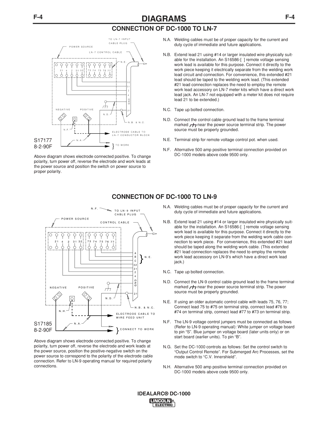
N.A. Welding cables must be of proper capacity for the current and duty cycle of immediate and future applications.

N.B. Extend lead 21 using #14 or larger insulated wire physically suit- able for the installation. An S16586-[ ] remote voltage sensing work lead is available for this purpose. Connect it directly to the work piece keeping it electrically separate from the welding work lead circuit and connection. For convenience, this extended #21 lead should be taped to the welding work lead. (This extended #21 lead connection replaces the need to employ the remote work lead accessory on LN-7 meter kits which have a direct work lead jack. An LN-7 not equipped with a meter kit does not require lead 21 to be extended.)

S17177

8-2-90F

N E G A T I V E

P O S I T I V E


N . D .

N . F .


N . A .

2 1

N . B . & N . C .

E L E C T R O D E C A B L E T O

L N - 7 C O N D U C T O R B L O C K

}T O W O R K

N.C. Tape up bolted connection.

N.D. Connect the control cable ground lead to the frame terminal

marked near the power source terminal strip. The power source must be properly grounded.

N.E. Terminal strip for remote voltage control pot. when used.

N.F. Alternative 500 amp positive terminal connection provided on DC-1000 models above code 9500 only.

Above diagram shows electrode connected positive. To change polarity, turn power off, reverse the electrode and work leads at the power source and position the switch on power source to proper polarity.

CONNECTION OF DC-1000 TO LN-9


N . F .


T O L N - 9 I N P U T


C A B L E P L U G


P O W E R S O U R C E


C O N T R O L C A B L E


7 3


2 1

4

2

3 1

3 2

7 4

7 5

7 6

7 7

3 2

}


A


B


N . E .

C

3 1

2

4

N.A. Welding cables must be of proper capacity for the current and duty cycle of immediate and future applications.

N.B. Extend lead 21 using #14 or larger insulated wire physically suit- able for the installation. An S16586-[ ] remote voltage sensing work lead is available for this purpose. Connect it directly to the work piece keeping it separate from the welding work cable con- nection to work piece. For convenience, this extended #21 lead should be taped along the welding work cable. (This extended #21 lead connection replaces the need to employ the remote work lead accessory on LN-9’s which have a direct work lead jack.)

N.C. Tape up bolted connection.

N E G A T I V E

P O S I T I V E


N . D .

N . H .


S17185

N . A .

8-2-90F


DN

G

2 1

N . B . & N . C .

E L E C T R O D E C A B L E T O W I R E F E E D U N I T

} C O N N E C T T O W O R K

N.D. Connect the LN-9 control cable ground lead to the frame terminal

marked near the power source terminal strip. The power source must be properly grounded.

N.E. If using an older automatic control cable with leads 75, 76, 77; Connect lead 75 to #75 on terminal strip, connect lead #76 to #74 on terminal strip, connect lead #77 to #73 on terminal strip.

N.F. The LN-9 voltage control jumpers must be connected as follows (Refer to LN-9 operating manual): White jumper on voltage board to pin “S”. Blue jumper on voltage board (later units only) or on start board (earlier units). To pin “B”.

Above diagram shows electrode connected positive. To change polarity, turn power off, reverse the electrode and work leads at the power source, position the positive-negative switch on the power source to correspond to the polarity of the electrode cable connection. Refer to LN-9 operating manual for required polarity connections.

N.G. Set the DC-1000 controls as follows: Set the control switch to “Output Control Remote”. For Submerged Arc Processes, set the mode switch to “C.V. Innershield”.

N.H. Alternative 500 amp positive terminal connection provided on DC-1000 models above code 9500 only.

IDEALARC® DC-1000

Page 27
Image 27
Lincoln Electric IM420-D manual Connection of DC-1000 to LN-9, S17177 90F, S17185 90F

IM420-D specifications

The Lincoln Electric IM420-D is a high-performance industrial welding machine that offers advanced features and technologies tailored for demanding welding environments. Designed for arc welding applications, the IM420-D is a versatile solution suitable for various welding processes, including MIG, TIG, and stick welding. This flexibility makes it an excellent choice for both professional welders and industries that require a reliable and efficient welding system.

One of the standout features of the IM420-D is its impressive output range. With a maximum output of 420 amps, this machine can handle thick materials and deliver deep penetration, making it ideal for heavy-duty applications. The machine also provides consistent arc stability, ensuring high-quality welds with minimal spatter. This functionality is essential in maintaining productivity and reducing the need for post-weld cleanup.

The IM420-D incorporates advanced digital control technology that enhances user experience and precision. The intuitive interface allows operators to quickly adjust settings for voltage, wire feed speed, and other parameters, ensuring optimal performance for diverse welding tasks. Additionally, the machine is equipped with a memory function that saves preferred settings, enabling quick setup for repetitive jobs.

Another notable characteristic of the IM420-D is its robust construction. Built to withstand the rigors of a manufacturing environment, the machine features a durable casing designed to protect key components from dust, moisture, and impact. This reliability results in fewer maintenance issues and extended service life, contributing to lower operational costs over time.

The IM420-D also includes a range of safety features that prioritize operator protection. Overheat protection, voltage fluctuation safeguards, and high-quality electrical insulation ensure a safe working environment, minimizing the risk of accidents during operation.

In conclusion, the Lincoln Electric IM420-D is an exceptional welding machine that combines high output, advanced digital technology, and robust design. With its user-friendly controls and safety features, it meets the needs of professional welders and industries seeking efficiency and quality in their welding operations. Whether for manufacturing, construction, or repair work, the IM420-D stands out as a top-tier choice in the welding equipment market.