|
|
|
|
| Next |
|
Step | Test |
| Test | Conclusion | Test | Repair Action |
Check | Result | Step | ||||
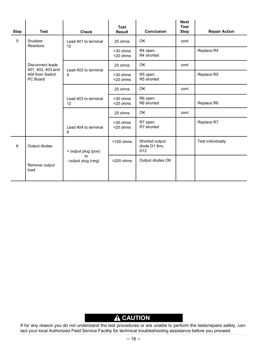
5 | Snubber | Lead 401 to terminal | 25 ohms | OK | cont |
|
| Resistors | 12 |
|
|
|
|
| >30 ohms | R4 open |
| Replace R4 | ||
|
|
|
| |||
|
|
| <20 ohms | R4 shorted |
|
|
|
|
|
|
|
|
|
| Disconnect leads |
| 25 ohms | OK | cont |
|
| 401, 402, 403 and | Lead 402 to terminal |
|
|
|
|
|
|
|
|
| ||
| 404 from Switch | 9 | >30 ohms | R5 open |
| Replace R5 |
| PC Board |
| <20 ohms | R5 shorted |
|
|
|
|
|
|
|
|
|
|
|
| 25 ohms | OK | cont |
|
|
|
|
|
|
|
|
|
| Lead 403 to terminal | >30 ohms | R6 open |
|
|
|
| 12 | <20 ohms | R6 shorted |
| Replace R6 |
|
|
|
|
|
|
|
|
|
| 25 ohms | OK | cont |
|
|
|
|
|
|
|
|
|
|
| >30 ohms | R7 open |
| Replace R7 |
|
| Lead 404 to terminal | <20 ohms | R7 shorted |
|
|
|
| 9 |
|
|
|
|
|
|
|
|
|
|
|
|
|
| <100 ohms | Shorted output |
| Test individually |
6 | Output diodes |
|
| diode D1 thru |
|
|
|
| + output plug (pos) |
| D12 |
|
|
|
| to |
|
|
|
|
|
|
| Output diodes OK |
|
| |
| Remove output | - output plug (neg) | >200 ohms |
|
| |
|
|
|
|
|
| |
| load |
|
|
|
|
|
|
|
|
|
|
|
|
![]() CAUTION
CAUTION
If for any reason you do not understand the test procedures or are unable to perform the tests/repairs safely, con- tact your local Authorized Field Service Facility for technical troubleshooting assistance before you proceed.
– 18 –
