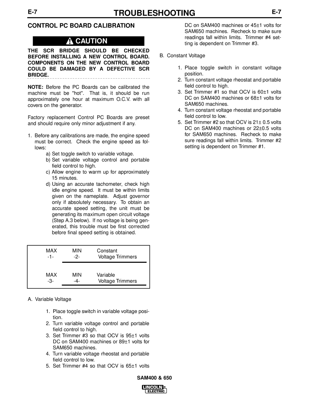
SAM650, SAM400 specifications
Lincoln Electric has long been synonymous with welding excellence, and its SAM series of advanced welding machines, including the SAM400 and SAM650, epitomizes this commitment to quality and innovation. These models are designed to meet the demands of diverse industrial applications while ensuring ease of use, efficiency, and precision.The SAM400 is a robust multiprocess welding system that supports MIG, TIG, Stick, and Flux-Cored welding techniques. It features a powerful 400 Amp output, suitable for heavy-duty applications and capable of handling materials such as steel, stainless steel, and aluminum. The machine incorporates advanced inverter technology, resulting in a compact design that significantly reduces the weight while enhancing portability. Furthermore, the SAM400 includes intuitive digital controls, allowing operators to easily adjust settings for optimal performance. Its PAS (Power Adapter System) compatibility enables users to seamlessly integrate different power sources, greatly enhancing its versatility.
On the other hand, the SAM650 takes it a step further, boasting a maximum output of 650 Amps. This model is particularly favored in industries requiring high deposition rates, such as shipbuilding and heavy fabrication. Like the SAM400, the SAM650 features multiprocess capabilities but adds enhanced control mechanisms, such as advanced waveform technology, which allows for better arc stability and reduced spatter. This ensures cleaner welds and, ultimately, a superior finish. Additionally, the SAM650 is equipped with Lincoln Electric's proprietary welding technology, including the Arc Control and Hot Start features that enhance user experience by providing smoother starts and consistent performance, even in challenging conditions.
Both machines come with integrated wire feeders that allow for easy adjustments and quick material changes, offering increased productivity on the job site. Their rugged design and durable construction ensure long-lasting performance, even in the harshest environments.
In conclusion, the Lincoln Electric SAM400 and SAM650 welding systems are trailblazers in the field of welding technology. With their powerful output, advanced features, and user-friendly interfaces, these machines cater to the needs of professionals looking for reliability and efficiency in their welding applications. Whether for small shops or large-scale industrial operations, the SAM400 and SAM650 deliver the performance and versatility that fabricators and welders depend on.

