Return to Section TOC

Return to Section TOC

Return to Section TOC

Return to Section TOC

Return to Master TOC

Return to Master TOC

Return to Master TOC

Return to Master TOC


A-3

INSTALLATION


A-3


SAFETY PRECAUTIONS


For K316L-2or higher (8 pin connector)


WARNING


With the power source turned off,

install the input


ELECTRIC SHOCK can kill.


cable per the following instructions:


• Only qualified personnel should per-


The K316L-2 LN-23P can be connected directly to


form this installation,

maintenance


any Lincoln power source that has CV output. and


and troubleshooting work.


Twist-Mate weld terminals (V350, V350-PIPE, CV-


305, etc..),

using the control cable provided with the


• Turn off the input power at the fuse box before


machine.


working on other equipment connected to the


• Connect the 14-pin connector and Twist-Mate plug of


welding system at the disconnect switch or fuse


box before working on this equipment.


the input cable assembly to the front of the welder.


• Do not touch electrically hot parts.


Unclip the rubber retaining strap that holds the wire

------------------------------------------------------------------------


enclosure cover in place, and remove the cover.


INPUT CABLE:


rear of the LN-23P and open the door. Route the


For K316L-1(6 pin connector)


Push the wire drive section door latch towards the


electrode cable through the large rubber grommet in


The standard 25 foot input cable between the LN-23P


the rear of the wire feed section and connect the lug


and the power source (with a K350 Adapter Kit) con-


to the brass conductor block at the front of the motor


sists of a six-conductor control cable and a 1/0 elec-


gear box assembly using the bolt provided. Attach


trode cable. The control cable has lugged leads on the


the control cable strain relief hook to the bracket on


power source end and a polarized plug on the wire


the frame of the LN-23P.


feeder end.


Connect the 8-pin receptacle to the LN-23P located


With the power source turned off, install the input


on the back underside of the control box.


cable per the following instructions:


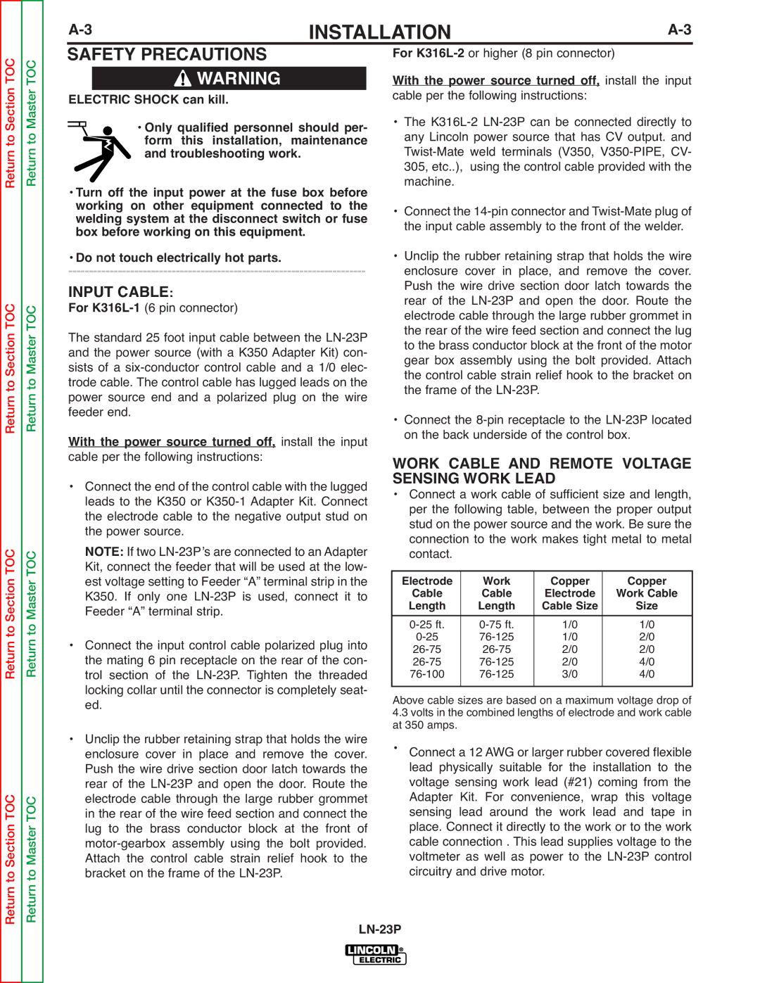
WORK CABLE AND REMOTE VOLTAGE


• Connect the end of the control cable with the lugged


SENSING WORK LEAD


• Connect a work cable of sufficient size and length,


leads to the K350 or K350-1 Adapter Kit. Connect


per the following table, between the proper output


the electrode cable to the negative output stud on


stud on the power source and the work. Be sure the


the power source.


connection to the work makes tight metal to metal


NOTE: If two LN-23Pʼs are connected to an Adapter


contact.


Kit, connect the feeder that will be used at the low-


est voltage setting to Feeder “A” terminal strip in the


Electrode


Work


Copper


Copper


K350. If only one LN-23P is used, connect it to


Cable


Cable


Electrode


Work Cable


Length


Length


Cable Size


Size


Feeder “A” terminal strip.


0-25 ft.


0-75 ft.


1/0


1/0


• Connect the input control cable polarized plug into


0-25


76-125


1/0


2/0


26-75


26-75


2/0


2/0


the mating 6 pin receptacle on the rear of the con-


26-75


76-125


2/0


4/0


trol section of the LN-23P. Tighten the threaded


76-100


76-125


3/0


4/0


locking collar until the connector is completely seat-


Above cable sizes are based on a maximum voltage drop of


ed.


4.3 volts in the combined lengths of electrode and work cable


• Unclip the rubber retaining strap that holds the wire


at 350 amps.


Connect a 12 AWG or larger rubber covered flexible


enclosure cover in place and remove the cover.


Push the wire drive section door latch towards the


lead physically suitable for the installation to the


rear of the LN-23P and open the door. Route the


voltage sensing work lead (#21) coming from the


electrode cable through the large rubber grommet


Adapter Kit. For convenience, wrap this voltage


in the rear of the wire feed section and connect the


sensing lead around the work lead and tape in


lug to the brass conductor block at the front of


place. Connect it directly to the work or to the work


motor-gearbox assembly using the bolt provided.


cable connection . This lead supplies voltage to the


Attach the control cable strain relief hook to the


voltmeter as well as power to the LN-23P control


bracket on the frame of the LN-23P.


circuitry and drive motor.


LN-23P

Page 9
Image 9
Lincoln Electric SVM176-A service manual Safety Precautions, Input Cable, Work Cable and Remote Voltage, Sensing Work Lead

SVM176-A specifications

The Lincoln Electric SVM176-A is a robust and versatile semiautomatic wire feeder designed to cater to a wide range of welding applications. Known for its reliability and ease of use, the SVM176-A is particularly favored in both industrial and construction settings, where efficiency and performance are paramount.

One of the standout features of the SVM176-A is its compact design. This relatively lightweight unit is easy to transport and can fit into tight spaces, making it an ideal choice for mobile applications or projects that require more maneuverability. The unit's construction is durable and built to withstand the rigors of demanding work environments, ensuring longevity and consistent performance.

The SVM176-A supports various welding processes, including MIG (Metal Inert Gas) and flux-cored arc welding, providing versatility for different materials and thicknesses. This adaptability is enhanced by its ability to accommodate a variety of wire sizes, allowing users to select the ideal wire type for their specific project requirements. The equipment also features adjustable wire feed speed, helping to ensure optimal weld quality by allowing operators to tailor their settings based on the needs of the job.

Innovative technologies in the SVM176-A contribute to its performance. The unit is equipped with a digitally controlled microprocessor that streamlines operations, providing enhanced control over welding parameters. This advanced technology enables users to achieve precise welds consistently, minimizing the risk of defects and improving overall efficiency.

Another remarkable characteristic of the SVM176-A is its user-friendly interface. The unit features easy-to-read displays and intuitive controls, enabling operators to make quick adjustments without having to consult an extensive manual. This is particularly beneficial in fast-paced work environments where time is of the essence.

Furthermore, the Lincoln Electric SVM176-A boasts a range of safety features, including thermal overload protection and a sturdy casing, which safeguard both the equipment and the operator. With these characteristics combined, the SVM176-A stands out as a preferred choice for professional welders seeking reliability, versatility, and operational excellence in their equipment. This exceptional wire feeder continues to uphold Lincoln Electric's commitment to quality and performance in welding technology.