INSTALLATION INSTRUCTIONS
POWER ADAPTER CABLE
Model 1092-06
WARNING:
∙Disconnect power before any installation or repair.
∙ Wear safety glasses.
The Model
To Connect a Three-Tab Receiver:
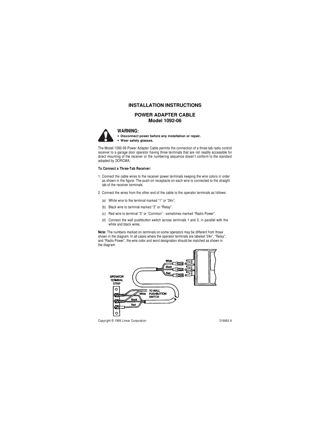
1.Connect the cable wires to the receiver power terminals keeping the wire colors in order as shown in the figure. The
2.Connect the wires from the other end of the cable to the operator terminals as follows:
(a)White wire to the terminal marked “1” or “24v”.
(b)Black wire to terminal marked “2” or “Relay”.
(c)Red wire to terminal “3” or “Common” - sometimes marked “Radio Power”.
(d)Connect the wall pushbutton switch across terminals 1 and 2, in parallel with the white and black wires.
Note: The numbers marked on terminals on some operators may be different from those shown in the diagram. In all cases where the operator terminals are labeled “24v”, “Relay”, and “Radio Power”, the wire color and word designation should be matched as shown in the diagram.
Copyright © 1999 Linear Corporation | 216665 A |