14
COM | 24VAC | ILOCK | SINGLE | COM | PHOTO | NCREV | NOREV | COM | STOP | CLOSE |
|
|
|
|
|
|
|
|
|
|
|
OPEN INSTALLATION INSTRUCTIONS
ENTRAPMENT PROTECTION DEVICES WIRING INSTRUCTIONS
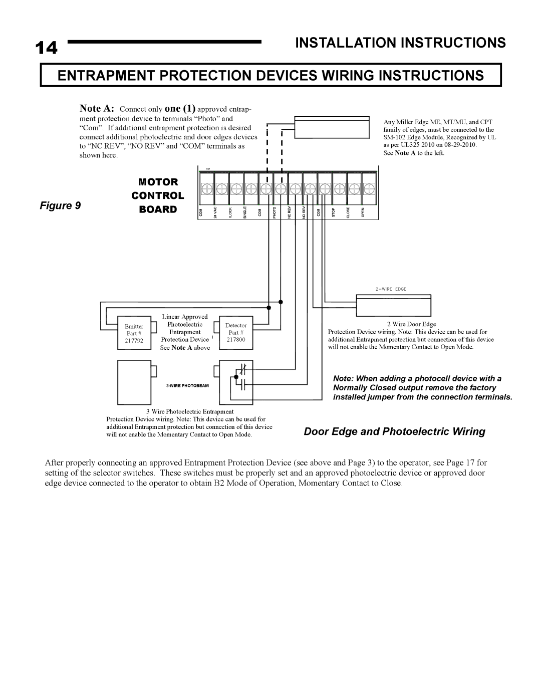
Note A: Connect only one (1) approved entrap-
ment protection device to terminals “Photo” and![]() “Com”. If additional entrapment protection is desired
“Com”. If additional entrapment protection is desired![]()
connect additional photoelectric and door edges devices to “NC REV”, “NO REV” and “COM” terminals as
shown here.
SAFE FINISH PHOTOBEAM
Any Miller Edge ME, MT/MU, and CPT family of edges, must be connected to the
See Note A to the left.
MOTOR
CONTROL
Figure 9 3-WIRE PHOTOBEAMBOARD
|
|
|
|
|
| OPEN | CLOSE | STOP |
|
|
|
| TB1 |
|
|
|
|
|
|
|
|
|
|
COM | 24 VAC | ILOCK | SINGLE | COM | PHOTO | NC REV | NO REV | COM | STOP | CLOSE | OPEN |
Linear Approved
Emitter | Photoelectric | Detector |
Part # | Entrapment | Part # |
217792 | Protection Device | 217800 |
| See Note A above |
|
3 Wire Photoelectric Entrapment Protection Device wiring. Note: This device can be used for additional Entrapment protection but connection of this device will not enable the Momentary Contact to Open Mode.
2 Wire Door Edge
Protection Device wiring. Note: This device can be used for additional Entrapment protection but connection of this device will not enable the Momentary Contact to Open Mode.
Note: When adding a photocell device with a Normally Closed output remove the factory installed jumper from the connection terminals.
Door Edge and Photoelectric Wiring
After properly connecting an approved Entrapment Protection Device (see above and Page 3) to the operator, see Page 17 for setting of the selector switches. These switches must be properly set and an approved photoelectric device or approved door edge device connected to the operator to obtain B2 Mode of Operation, Momentary Contact to Close.