ProComSol, Ltd |
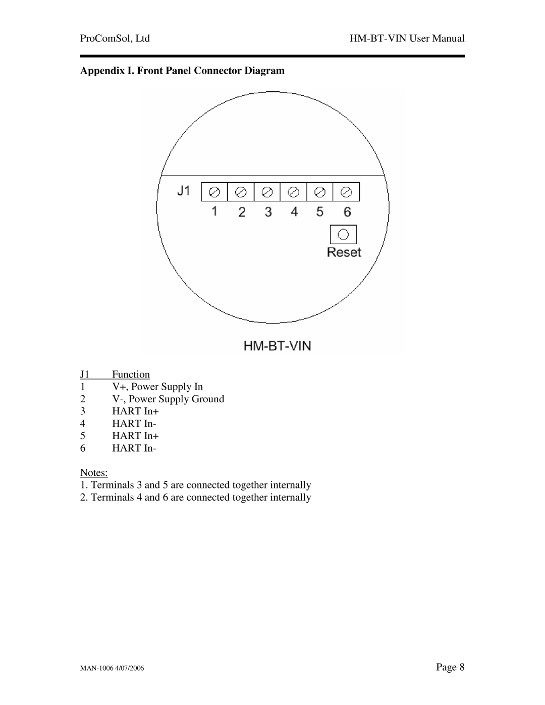
Appendix I. Front Panel Connector Diagram
J1 Function
1V+, Power Supply In
2
3 HART In+
4 HART In-
5 HART In+
6 HART In-
Notes:
1.Terminals 3 and 5 are connected together internally
2.Terminals 4 and 6 are connected together internally
Page 8 |