ProComSol, Ltd |
Power Connection:
Reset Switch
A reset switch is provided on the front panel to reset the
Press and hold the switch for 5 seconds to perform a reset.
Power LED
When the unit is powered, the Red LED will be on.
Bluetooth Activity LED
This Blue LED will flicker when the Bluetooth connection is open. The LED will be solid on when successfully linked to a Bluetooth transmitter. Under normal HART communication conditions, the LED will be solid on.
HART Connections
There are several ways to make the HART connection. Your specific situation will determine the best connection method to use to reduce installation time.
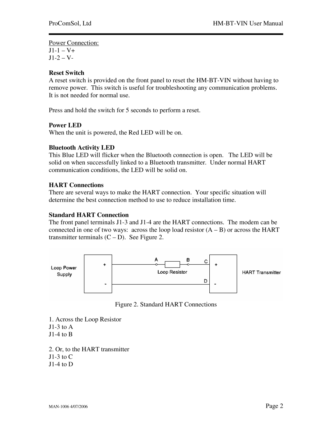
Standard HART Connection
The front panel terminals
Figure 2. Standard HART Connections
1.Across the Loop Resistor
J1-3 to A
J1-4 to B
2.Or, to the HART transmitter
J1-3 to C
J1-4 to D
Page 2 |