Instruction Manual | SAW FENCE KIT | Model |
|
|
|
Assembly Procedure (continued)
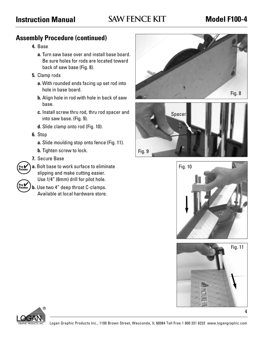
4.Base
a.Turn saw base over and install base board. Be sure holes for rods are located toward back of saw base (Fig. 8).
5.Clamp rods
a.With rounded ends facing up set rod into hole in base board.
b.Align hole in rod with hole in back of saw base.
c.Install screw thru rod, thru rod spacer and into saw base. (Fig. 9).
d.Slide clamp onto rod (Fig. 10).
6.Stop
a.Slide moulding stop onto fence (Fig. 11).
b.Tighten screw to lock.
7.Secure Base
![]()
![]() ✔ a. Bolt base to work surface to eliminate slipping and make cutting easier. Use 1/4” (6mm) drill for pilot hole.
✔ a. Bolt base to work surface to eliminate slipping and make cutting easier. Use 1/4” (6mm) drill for pilot hole.
![]() ✔
✔![]() b. Use two 4” deep throat
b. Use two 4” deep throat
Fig. 8
Spacer
Fig. 9
Fig. 10
Fig. 11
4
Logan Graphic Products Inc., 1100 Brown Street, Wauconda, IL 60084 Toll Free 1 800 331 6232 www.logangraphic.com