SETTING THE IMPEDANCE MATCHING JUMPERS
The impedance matching jumpers are located under a clear mylar cover on the right side of the top of the unit. Remove the two screws for access. The proper placement of these jumpers depends on the number of RAT1's and speakers used in the total installation. To set them for the best impedance matching condition, refer to the following charts and procedures:
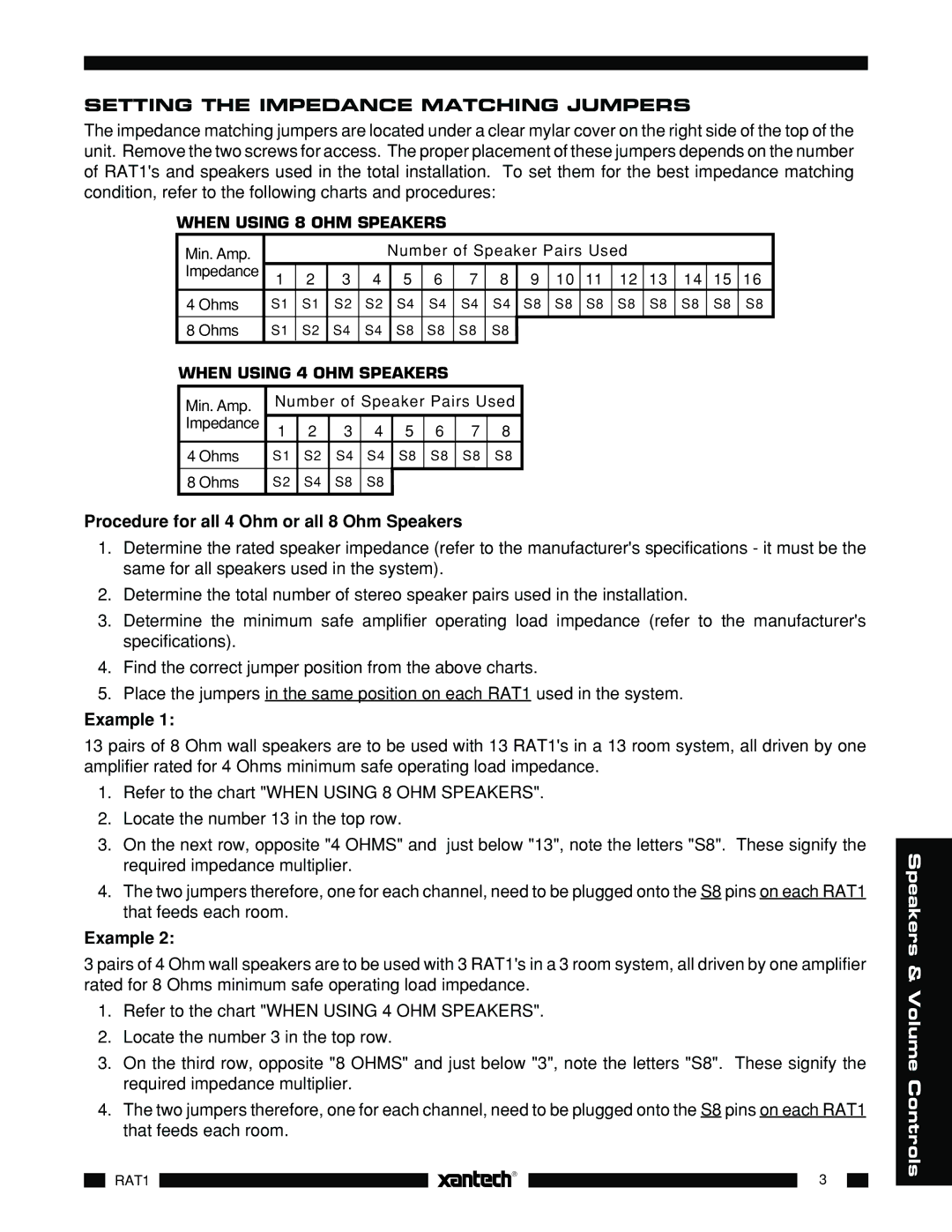
WHEN USING 8 OHM SPEAKERS |
|
|
|
|
|
|
|
|
|
|
|
|
|
|
| |||||||||||
| Min. Amp. |
|
|
|
|
|
| Number of Speaker Pairs Used |
|
|
|
|
| |||||||||||||
| Impedance | 1 | 2 | 3 | 4 |
| 5 | 6 | 7 | 8 | 9 | 10 | 11 | 12 | 13 | 14 | 15 | 16 |
| |||||||
|
|
|
| |||||||||||||||||||||||
| 4 Ohms |
| S1 | S1 | S2 |
| S2 |
| S4 |
| S4 |
| S4 |
| S4 |
|
| S8 | S8 | S8 | S8 | S8 | S8 | S8 | S8 | |
|
|
|
|
|
|
|
|
|
|
|
|
|
|
|
|
|
|
|
|
|
|
|
|
|
| |
| 8 Ohms |
| S1 | S2 | S4 |
| S4 | S8 |
| S8 |
| S8 |
| S8 |
|
|
|
|
|
|
|
|
|
|
| |
WHEN USING 4 OHM SPEAKERS |
|
|
|
|
|
|
|
|
|
|
|
|
|
|
| |||||||||||
| Min. Amp. |
| Number of Speaker Pairs Used |
|
|
|
|
|
|
|
|
|
|
| ||||||||||||
| Impedance | 1 | 2 | 3 |
| 4 |
| 5 |
| 6 |
| 7 |
| 8 |
|
|
|
|
|
|
|
|
|
|
| |
|
|
|
|
|
|
|
|
|
|
|
|
|
|
|
|
|
| |||||||||
| 4 Ohms |
| S1 | S2 | S4 |
| S4 |
| S8 |
| S8 |
| S8 |
| S8 |
|
|
|
|
|
|
|
|
|
|
|
|
|
|
|
|
|
|
|
|
|
|
|
|
|
|
|
|
|
|
|
|
|
|
|
|
|
|
| 8 Ohms |
| S2 | S4 | S8 |
| S8 |
|
|
|
|
|
|
|
|
|
|
|
|
|
|
|
|
|
|
|
|
|
|
|
|
|
|
|
|
|
|
|
|
|
|
|
|
|
|
|
|
|
|
|
|
|
|
Procedure for all 4 Ohm or all 8 Ohm Speakers
1.Determine the rated speaker impedance (refer to the manufacturer's specifications - it must be the same for all speakers used in the system).
2.Determine the total number of stereo speaker pairs used in the installation.
3.Determine the minimum safe amplifier operating load impedance (refer to the manufacturer's specifications).
4.Find the correct jumper position from the above charts.
5.Place the jumpers in the same position on each RAT1 used in the system.
Example 1:
13 pairs of 8 Ohm wall speakers are to be used with 13 RAT1's in a 13 room system, all driven by one amplifier rated for 4 Ohms minimum safe operating load impedance.
1.Refer to the chart "WHEN USING 8 OHM SPEAKERS".
2.Locate the number 13 in the top row.
3.On the next row, opposite "4 OHMS" and just below "13", note the letters "S8". These signify the required impedance multiplier.
4.The two jumpers therefore, one for each channel, need to be plugged onto the S8 pins on each RAT1 that feeds each room.
Example 2:
3 pairs of 4 Ohm wall speakers are to be used with 3 RAT1's in a 3 room system, all driven by one amplifier rated for 8 Ohms minimum safe operating load impedance.
1.Refer to the chart "WHEN USING 4 OHM SPEAKERS".
2.Locate the number 3 in the top row.
3.On the third row, opposite "8 OHMS" and just below "3", note the letters "S8". These signify the required impedance multiplier.
4.The two jumpers therefore, one for each channel, need to be plugged onto the S8 pins on each RAT1 that feeds each room.
| |
| 3 |
|
RAT1 |
|
|
| |
|
|
|
|
|
|
|
|
|
|
Speakers & Volume Controls