| INSTALLATION (cont'd) |
| |
Serial Combiner | Serial Combiner |
CONTROLLED COMPONENTS
Satellite Receiver
2 3 4 5 | CONTROL INPUTS | SERIAL CONTROL | COMBINER | I T Y |
| 0 | |
1 |
|
|
|
| A R O R |
| 8 9 1 |
|
|
|
|
| L T |
| 7 |
|
|
|
|
| O C |
| 6 |
|
|
|
|
| P E |
| 5 |
|
|
|
|
| O G I C S E L | ON | 1 2 3 4 |
|
|
|
|
| L |
|
|
OUTPUTS
CONTROL
A B
2 3 4 5 | CONTROL INPUTS | COMBINER | I T Y |
| 0 | |
1 |
|
|
| A R O R |
| 8 9 1 |
|
|
|
| L T |
| 7 |
|
|
|
| O C |
| 6 |
|
|
|
| P E |
| 5 |
|
|
|
| O G I C S E L | ON | 1 2 3 4 |
|
|
|
| L |
|
|
OUTPUTS
CONTROL
A B
|
|
| |
| Connecting Block | ||
| 12VDC | 789 CONNECTING |
|
| +12 VDC |
| |
– | GND | EMITTERS | |
| |||
| STATUS | ||
![]() 283M
283M
CD Changer
283M
|
|
| ||
To IR IN | connection. Use | To IR IN | Use | |
3.5/3.5mm Mini- | ||||
and GND | Plug cable, | and GND | ||
end cables, | ||||
on each RAT1 | Pt. # 6017400 | on each RAT1 | ||
Pt. # 6015900 | ||||
|
|
|
|
|
| - | |
+ | IR IN |
| 44 BLOCK | |
| ® | |||
White | IR RCVR | |||
Stripped | ||||
|
|
| ||
Side (+) |
|
|
|
To additional Emitters if needed
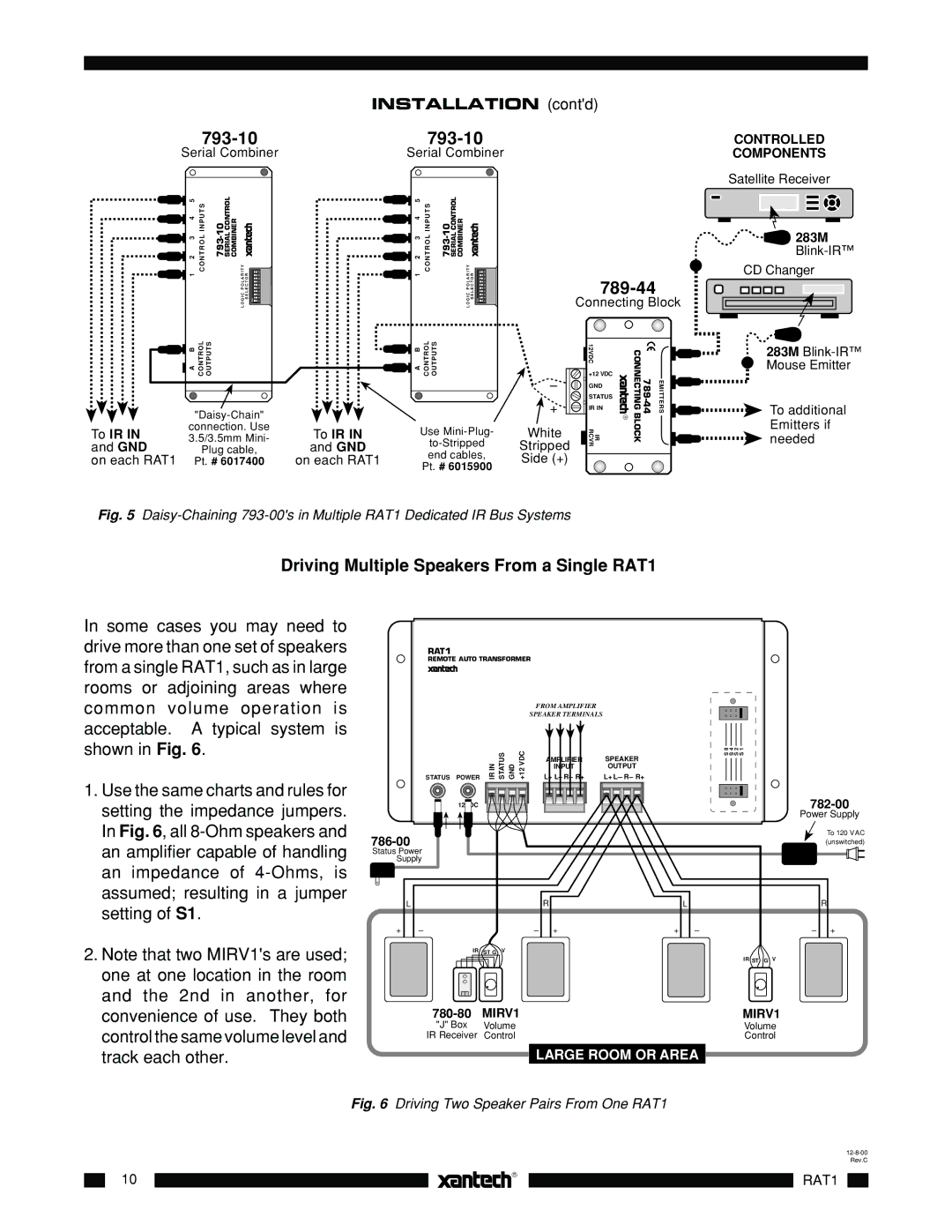
Fig. 5 Daisy-Chaining 793-00's in Multiple RAT1 Dedicated IR Bus Systems
Driving Multiple Speakers From a Single RAT1
In some cases you may need to drive more than one set of speakers from a single RAT1, such as in large rooms or adjoining areas where common volume operation is acceptable. A typical system is shown in Fig. 6.
1.Use the same charts and rules for setting the impedance jumpers. In Fig. 6, all
2.Note that two MIRV1's are used; one at one location in the room and the 2nd in another, for convenience of use. They both control the same volume level and track each other.
RAT1 |
|
|
|
|
REMOTE AUTO TRANSFORMER |
| |||
|
|
| FROM AMPLIFIER |
|
|
|
| SPEAKER TERMINALS |
|
STATUS | POWER | INIR STATUS GND +12VDC | L+ L– R– R+ | L+ L– R– R+ |
|
|
| AMPLIFIER | SPEAKER |
|
|
| INPUT | OUTPUT |
| 12VDC |
|
|
|
Status Power
Supply
| L |
| R |
| L |
+ | – | – | + | + | – |
| IR ST G | V |
|
|
|
MIRV1 | |
"J" Box | Volume |
IR Receiver | Control |
LARGE ROOM OR AREA
S 1
S 2
S 4
S 8
782-00
Power Supply
To 120 V AC (unswitched)
R
– +
IR ST G V
MIRV1
Volume
Control
Fig. 6 Driving Two Speaker Pairs From One RAT1
10 |
| |
| ||
|
| |
|
|
|
|
|
|