Pan Tilt Controller Interface Module
① | ② | ③ |
|
①CAMERA INPUT | ②DVR INPUT | ③6PIN DIP |
|
CONNECTOR | SWITCH |
| |
CONNECTOR |
| ||
|
|
| |
|
|
|
|
Port | Description |
| Connection Type |
|
|
| |
To Camera | 6 Pin DIN jack | ||
|
|
| |
To DVR | Serial data output / video output | 6 Pin DIN jack | |
|
|
|
|
SW 1 | Camera ID selection |
| 6 Pin DIP switch |
|
|
|
|
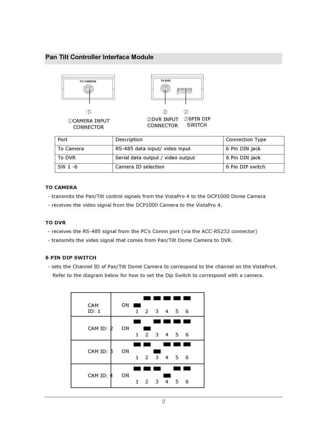
TO CAMERA
-transmits the Pan/Tilt control signals from the VistaPro 4 to the DCP1000 Dome Camera
-receives the video signal from the DCP1000 Camera to the VistaPro 4.
TO DVR
-receives the
-transmits the video signal that comes from Pan/Tilt Dome Camera to DVR.
6 PIN DIP SWITCH
-sets the Channel ID of Pan/Tilt Dome Camera to correspond to the channel on the VistaPro4. Refer to the diagram below for how to set the Dip Switch to correspond with a camera.
CAM |
| ON |
|
|
|
|
|
|
|
|
|
|
|
|
|
|
|
|
|
|
|
|
|
|
|
|
| ||
|
|
|
|
|
|
|
|
|
|
|
|
| ||
|
|
|
|
|
|
|
|
|
|
|
| |||
ID: 1 |
| 1 |
| 2 |
| 3 | 4 | 5 | 6 |
| ||||
|
|
|
|
|
|
|
|
|
|
|
|
|
|
|
|
|
|
|
|
|
|
|
|
|
|
|
| ||
|
|
|
|
|
|
|
|
|
|
|
|
|
|
|
CAM ID: 2 | ON |
|
|
|
|
|
|
|
|
|
| |||
|
|
|
|
|
|
|
|
|
| |||||
|
| 1 |
| 2 |
| 3 | 4 | 5 | 6 |
| ||||
|
|
|
|
|
|
|
|
|
|
|
|
|
|
|
|
|
|
|
|
|
|
|
|
|
|
| |||
|
|
|
|
|
|
|
|
|
|
|
|
|
|
|
CAM ID: 3 | ON |
|
|
|
|
|
|
|
|
|
| |||
|
|
|
|
|
|
|
|
|
| |||||
|
| 1 |
| 2 |
| 3 | 4 | 5 | 6 |
| ||||
|
|
|
|
|
|
|
|
|
|
|
|
|
|
|
|
|
|
|
|
|
|
|
|
|
|
| |||
|
|
|
|
|
|
|
|
|
|
|
|
|
| |
CAM ID: 4 | ON |
|
|
|
|
|
|
|
|
|
| |||
|
|
|
|
|
|
|
|
|
| |||||
|
| 1 |
| 2 |
| 3 | 4 | 5 | 6 |
| ||||
|
|
|
|
|
|
|
|
|
|
|
|
|
|
|
2
