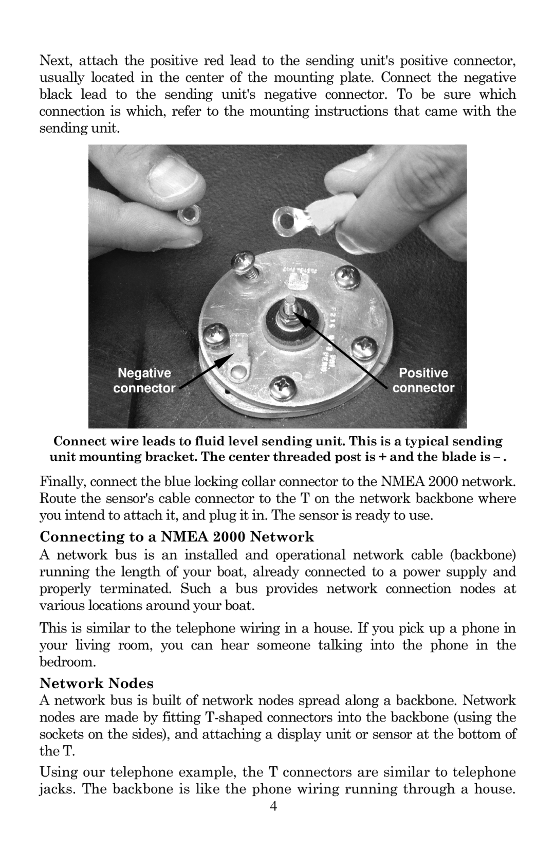
Next, attach the positive red lead to the sending unit's positive connector, usually located in the center of the mounting plate. Connect the negative black lead to the sending unit's negative connector. To be sure which connection is which, refer to the mounting instructions that came with the sending unit.
Negative | Positive |
connector | connector |
Connect wire leads to fluid level sending unit. This is a typical sending unit mounting bracket. The center threaded post is + and the blade is
Finally, connect the blue locking collar connector to the NMEA 2000 network. Route the sensor's cable connector to the T on the network backbone where you intend to attach it, and plug it in. The sensor is ready to use.
Connecting to a NMEA 2000 Network
A network bus is an installed and operational network cable (backbone) running the length of your boat, already connected to a power supply and properly terminated. Such a bus provides network connection nodes at various locations around your boat.
This is similar to the telephone wiring in a house. If you pick up a phone in your living room, you can hear someone talking into the phone in the bedroom.
Network Nodes
A network bus is built of network nodes spread along a backbone. Network nodes are made by fitting
Using our telephone example, the T connectors are similar to telephone jacks. The backbone is like the phone wiring running through a house.
4
