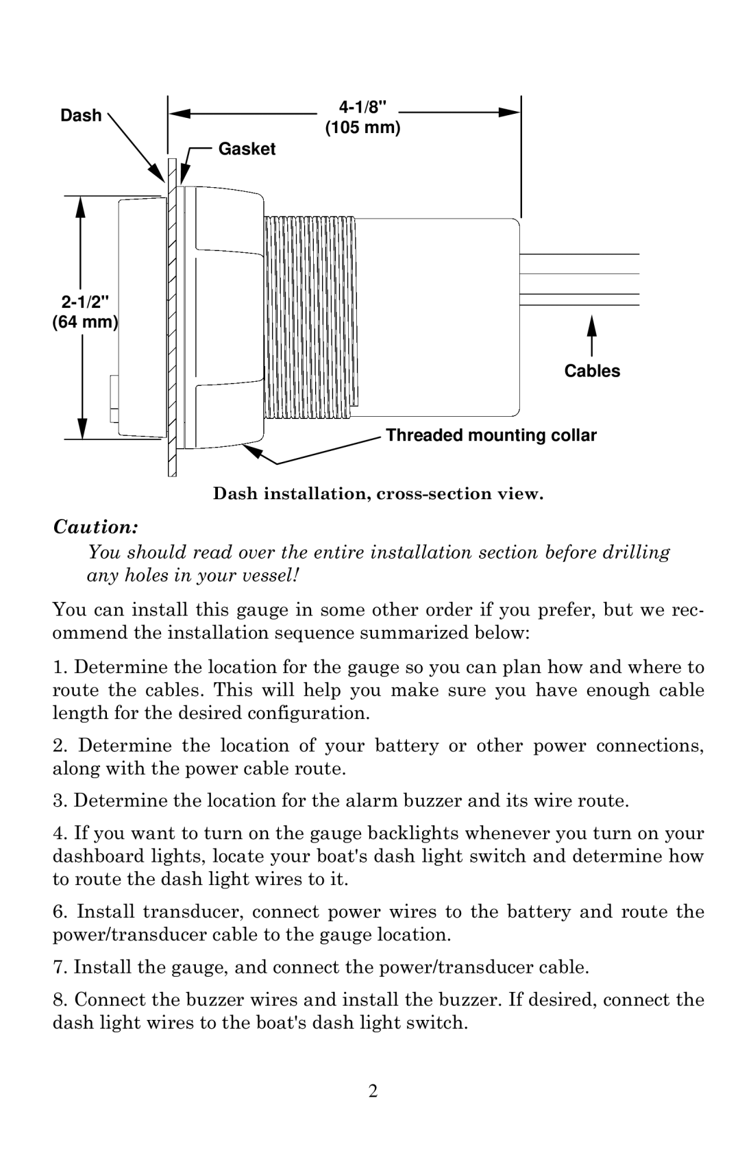
Dash
(64 mm)
Caution:
(105 mm)
 Gasket
Cables
Threaded mounting collar
Dash installation,
You should read over the entire installation section before drilling any holes in your vessel!
You can install this gauge in some other order if you prefer, but we rec- ommend the installation sequence summarized below:
1.Determine the location for the gauge so you can plan how and where to route the cables. This will help you make sure you have enough cable length for the desired configuration.
2.Determine the location of your battery or other power connections, along with the power cable route.
3.Determine the location for the alarm buzzer and its wire route.
4.If you want to turn on the gauge backlights whenever you turn on your dashboard lights, locate your boat's dash light switch and determine how to route the dash light wires to it.
6.Install transducer, connect power wires to the battery and route the power/transducer cable to the gauge location.
7.Install the gauge, and connect the power/transducer cable.
8.Connect the buzzer wires and install the buzzer. If desired, connect the dash light wires to the boat's dash light switch.
2