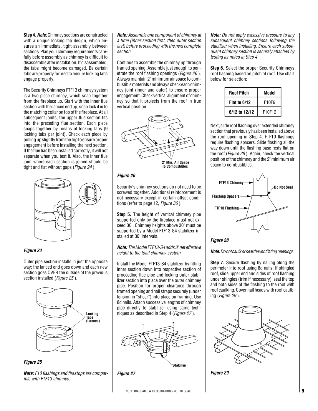
Step 4. Note: Chimney sections are constructed with a unique locking tab design, which en- sures an immediate, tight assembly between sections. Plan your chimney requirements care- fully before assembly as chimney is difficult to disassemble after installation. If disassembled, the tabs might become damaged. Be certain tabs are properly formed to ensure locking tabs engage properly.

The Security Chimneys FTF13 chimney system is a two piece chimney, which snap together from the fireplace up. Start with the inner flue section with the lanced end up, snap lock it in to the matching collar on top of the fireplace. At all subsequent joints, the upper flue section fits into the preceding flue section. Each piece snaps together by means of locking tabs (9 locking tabs per joint). Check each piece by pulling up slightly from the top to ensure proper engagement before installing the next section. If the flue has been installed correctly, it will not separate when you test it. Also, the inner flue joint where each section is joined should be tight and flat without gaps (Figure 24 ).

Figure 24

Outer pipe section installs in just the opposite way; the lanced end goes down and each new section goes OVER the outside of the previous section installed (Figure 25 ).

Locking Tabs (Lances)

Figure 25

Note: F10 flashings and firestops are compat- ible with FTF13 chimney.

Note: Assemble one component of chimney at a time (inner section first, then outer section last) before proceeding with the next complete section.

Continue to assemble the chimney up through framed opening. Assemble just enough to pen- etrate the roof flashing openings (Figure 26 ). Always maintain 2" minimum air space to com- bustible materials and always check each chim- ney joint (inner and outer) to ensure proper engagement. Check vertical alignment of chim- ney so that it projects from the roof in true vertical position.

2" Min. Air Space

To Combustibles

Figure 26

Security's chimney sections do not need to be screwed together. Additional reinforcement is not necessary except in certain offset condi- tions (refer to page 12, Figure 36 ).

Step 5. The height of vertical chimney pipe supported only by the fireplace must not ex- ceed 30'. Chimney heights above 30' must be supported by a Model FTF13-S4 stabilizer in- stalled at 30' intervals.

Note: The Model FTF13-S4 adds 3" net effective height to the total chimney system.

Install the Model FTF13-S4 stabilizer by fitting inner section down into respective section of proceeding flue pipe and locking outer stabi- lizer section into place over the outer chimney pipe. Position for proper clearance through framed opening and nail straps securely (under tension in “shear”) into place on framing. Use 8d nails. Attach successive lengths of chimney pipe directly to stabilizer using same tech- niques as described in Step 4 (Figure 27 ).

Stabilizer

Figure 27

NOTE: DIAGRAMS & ILLUSTRATIONS NOT TO SCALE.

Note: Do not apply excessive pressure to any subsequent chimney sections following the stabilizer when installing. Ensure each subse- quent chimney section is securely attached by testing as noted in Step 4.

Step 6. Select the proper Security Chimneys roof flashing based on pitch of roof. Use chart below for selection:

Roof Pitch

Model


Flat to 6/12

F10F6


6/12 to 12/12

F10F12


Next, slide roof flashing over extended chimney section that previously has been installed above the roof opening in Step 4. FTF10 flashings require flashing spacers. Slide flashing all the way down until the flashing base rests flat on the roof (Figure 28 ). Again, check the vertical position of the chimney and the 2" minimum air space to combustibles.

FTF13 Chimney

Do Not Seal

Flashing Spacers

FTF10 Flashing

Figure 28

Note:Do not caulk or seal the ventilating openings.

Step 7. Secure flashing by nailing along the perimeter into roof using 8d nails. If shingled roof, slide upper end and sides of roof flashing under shingles (trim if necessary), seal the top and both sides of the flashing to the roof with roof caulking. Cover nail heads with roof caulk- ing (Figure 29 ).

Figure 29

9

Page 9
Image 9
Lucent Technologies EST-48 installation instructions Roof Pitch Model Flat to 6/12, 12 to 12/12

EST-48 specifications

Lucent Technologies EST-48 is a cutting-edge telecommunications platform designed to enhance voice and data connectivity for enterprises and service providers alike. As a versatile solution, the EST-48 combines robust functionalities with advanced technology to meet the growing demands of modern communication infrastructures.

One of the main features of the EST-48 is its seamless integration capabilities. It allows organizations to unify their voice, video, and data services over a single network, thereby simplifying management and reducing operational costs. This integration is crucial for businesses looking to streamline their communication systems and improve collaboration among employees.

The EST-48 utilizes a modular architecture, providing flexibility and scalability to accommodate varying organizational needs. This modularity enables businesses to start with a basic configuration and expand their systems as they grow, adding new capabilities and services without significant disruptions. This characteristic is particularly beneficial for rapidly evolving enterprises.

In terms of technology, the EST-48 is equipped with advanced switching and routing capabilities, ensuring efficient data transmission and reduced latency. Its support for Voice over Internet Protocol (VoIP) technology allows for high-quality voice communications over the internet, significantly improving the clarity and reliability of calls. Additionally, the platform supports a variety of communication standards, making it compatible with existing infrastructure and third-party equipment.

Another significant characteristic of the EST-48 is its emphasis on security. The platform incorporates various security measures to protect sensitive data and prevent unauthorized access. This includes features such as encryption, secure access controls, and regular software updates to safeguard against potential vulnerabilities.

Moreover, the EST-48 comes with robust management tools that provide real-time monitoring and reporting capabilities. These tools enable administrators to track system performance, identify issues, and optimize the network for better efficiency.

In conclusion, Lucent Technologies EST-48 stands out as a versatile communications platform that combines advanced technology with user-friendly features. Its integration capabilities, modular design, emphasis on security, and management tools make it an ideal choice for organizations seeking to improve their communication systems in a cost-effective manner. As communication technology continues to evolve, platforms like the EST-48 will remain essential in meeting the needs of modern enterprises and service providers.