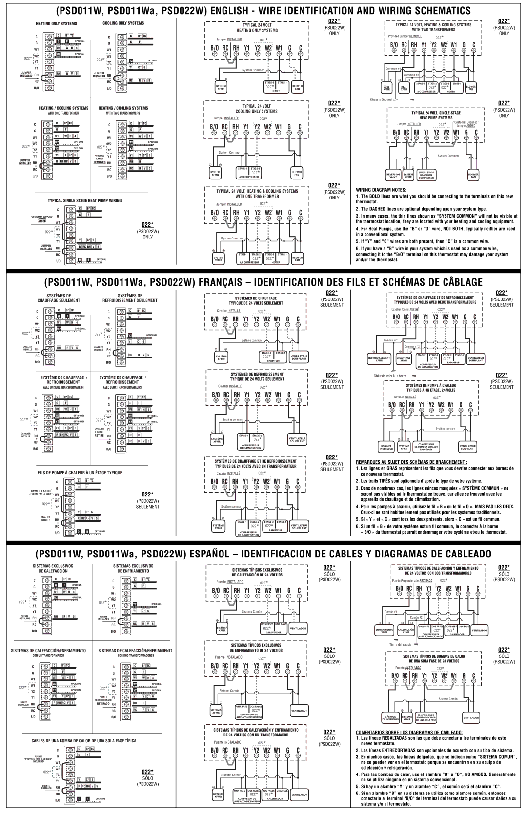
(PSD011W, PSD011Wa, PSD022W) ENGLISH - WIRE IDENTIFICATION AND WIRING SCHEMATICS

HEATING ONLY SYSTEMS

COOLING ONLY SYSTEMS


C

C

B* TC


C

C

B* TC


G

G

F


OPTIONAL


G

G

F


W1

W1

W

H

4


W1


022*

W2

W2


OPTIONAL


W2


Y2


022* Y2

Y2


OPTIONAL


Y1


Y1

Y1

C*

6


JUMPER

RH

RH

R

V

5

JUMPER

RH


INSTALLED


INSTALLED


RC


RC

RC

R

V

5


B/O


B/O


HEATING / COOLING SYSTEMS

HEATING / COOLING SYSTEMS

WITH ONE TRANSFORMER

WITH TWO TRANSFORMERS


C

C

B* TC


C

C

B* TC


G

G

F


G

G

F


W1

W1

W

H

4


W1

W1

W

H

4


022* W2Y2

W2


OPTIONAL

022* W2Y2

W2


OPTIONAL

Y2


OPTIONAL

Y2


OPTIONAL


Y1

Y1

Y

C*

6

PROVIDED

Y1

Y1

Y

C*

6

JUMPER


R

RH RC

V

5

JUMPER


RH

R


RH

REMOVED RH


INSTALLED


RC

RC

RC

R V 5

B/O

B/O


TYPICAL SINGLE STAGE HEAT PUMP WIRING

C

C

B* TC


“CUSTOMER SUPPLIED”

G

G

F

JUMPER


ADDED

W1


022*

022* W2Y2


(PSD022W)


Y

ONLY


Y1

C* 6


JUMPER

RH

R

RC RH

V

5

INSTALLED


RC

B/O

O

B

OPTIONAL


022*


TYPICAL 24 VOLT


(PSD022W)


HEATING ONLY SYSTEMS


ONLY


Jumper INSTALLED


022*


B/O

RC

RH

Y1

Y2 W2

W1

G

C


System Common


+

-


STAGE-2

STAGE-1


SYSTEM


022*


BLOWER

XFMR


FAN


HEATER


TYPICAL 24 VOLT


022*


(PSD022W)


COOLING ONLY SYSTEMS


Jumper INSTALLED


022*


ONLY


B/O

RC

RH

Y1

Y2 W2

W1

G

C

System Common

+-


STAGE-1

STAGE-2


SYSTEM


022*


BLOWER

XFMR


FAN


A/C COMPRESSOR


TYPICAL 24 VOLT, HEATING & COOLING SYSTEMS

022*


(PSD022W)


WITH ONE TRANSFORMER


ONLY


Jumper INSTALLED

022*


B/O RC

RH Y1

Y2

W2 W1

G

C


System Common

+-


STAGE-1

STAGE-2

STAGE-2

STAGE-1


SYSTEM


022*

022*


BLOWER

XFMR


FAN


A/C COMPRESSOR

HEATER


022*


TYPICAL 24 VOLT, HEATING & COOLING SYSTEMS

(PSD022W)


WITH TWO TRANSFORMERS


ONLY

Provided Jumper REMOVED

022*


B/O RC RH Y1 Y2

W2

W1 G

C


Common #1


Common #2


+

- +

-


STAGE-1 STAGE-2

STAGE-2

STAGE-1


COOL

HEAT


022*

022*


BLOWER


XFMR

XFMR


FAN


A/C COMPRESSOR

HEATER


Chassis Ground


022*


TYPICAL 24 VOLT, SINGLE-STAGE

(PSD022W)


ONLY


HEAT PUMP SYSTEMS


Jumper INSTALLED

022*


“Customer Supplied”


Jumper ADDED


B/O RC

RH Y1 Y2 W2

W1 G C


System Common


+

-


REVERSING

SYSTEM

SINGLE STAGE

BLOWER

HEAT PUMP

VALVE


XFMR

COMPRESSOR

FAN

WIRING DIAGRAM NOTES:

1.The BOLD lines are what you should be connecting to the terminals on this new thermostat.

2.The DASHED lines are optional depending upon your system type.

3.In many cases, the thin lines shown as “SYSTEM COMMON” will not be visible at the thermostat location, they are located with your heating and cooling equipment.

4.For Heat Pumps, use the “B” or “O” wire, NOT BOTH. Typically neither are used in a conventional system.

5.If “Y” and “C” wires are both present, then “C” is a common wire.

6.If you have a “B” wire in your system which is used as a common wire, connecting it to the “B/O” terminal on this thermostat may damage your system and/or the thermostat.

(PSD011W, PSD011Wa, PSD022W) FRANÇAIS – IDENTIFICATION DES FILS ET SCHÉMAS DE CÂBLAGE

SYSTÈMES DE

SYSTÈMES DE

CHAUFFAGE SEULEMENT

REFROIDISSEMENT SEULEMENT


C

C

B* TC


C

C

B* TC


G

G

F


OPTIONNEL


G

G

F


W1

W1

W

H

4


W1


022*

W2Y2

W2


OPTIONNEL

022* W2Y2


Y2


OPTIONNEL


Y1


Y1

Y1

C*

6


CAVALIER

RH

RH

R

V

5

CAVALIER

RH


INSTALLÉ


INSTALLÉ


RC


RC

RC

R

V

5


B/O


B/O


SYSTÈME DE CHAUFFAGE /

SYSTÈME DE CHAUFFAGE /

REFROIDISSEMENT

REFROIDISSEMENT

AVEC UN SEUL TRANSFORMATEUR

AVEC DEUX TRANSFORMATEURS


C

C

B*

TC


C

C

B* TC


G

G

F


G

G

F


W1

W1

W

H

4


W1

W1

W

H

4


022*

W2Y2

W2


OPTIONNEL

022* W2Y2

W2


OPTIONNEL

Y2


OPTIONNEL

Y2


OPTIONNEL


Y1

Y1

Y

C*

6

CAVALIER

Y1

Y1

Y

C*

6


FOURNI


CAVALIER


R RH RC

V

5


RH

R


RH

RETIRÉ

RH


INSTALLÉ


RC

RC

RC

R V 5

B/O

B/O


SYSTÈMES DE CHAUFFAGE

TYPIQUE DE 24 VOLTS SEULEMENT

Cavalier INSTALLÉ


022*


B/O

RC

RH

Y1

Y2

W2

W1

G

C


Système commun


+

-


ÉTAGE-2

ÉTAGE-1


SYSTÈME


022*


VENTILATEUR

XFMR


SOUFFLANT


RADIATEUR


SYSTÈMES DE REFROIDISSEMENT


TYPIQUE DE 24 VOLTS SEULEMENT


Cavalier INSTALLÉ

022*


B/O

RC

RH

Y1

Y2

W2

W1

G

C

Système commun

+-


ÉTAGE-1


ÉTAGE-2


SYSTÈME


022*

VENTILATEUR

XFMR


SOUFFLANT


COMPRESSEUR

DE CLIMATISATION

022*

(PSD022W)

SEULEMENT

022*

(PSD022W)

SEULEMENT

022*

SYSTÈMES DE CHAUFFAGE ET DE REFROIDISSEMENT

TYPIQUES DE 24 VOLTS AVEC DEUX TRANSFORMATEURS


Cavalier fourni RETIRÉ

022*


B/O RC RH Y1 Y2

W2

W1

G

C


Commun n° 1


Commun n° 2


+

-

+

-


ÉTAGE-1 ÉTAGE-2

ÉTAGE-2

ÉTAGE-1


REFROIDISSEMENT

CHAUFFAGE

022

022


VENTILATEUR


XFMR

XFMR

*

RADIATEUR*


SOUFFLANT


COMPRESSEUR


DE CLIMATISATION


Châssis mis à la terre


SYSTÈMES DE POMPE À CHALEUR


TYPIQUES À UN ÉTAGE, 24 VOLTS


Cavalier INSTALLÉ

022*


B/O

RC

RH Y1

Y2

W2 W1

G

C


Système commun


+

-


ROBINET

SYSTÈME

COMPRESSEUR

VENTILATEUR

DE POMPE À CHALEUR

INVERSEUR


XFMR

À UN ÉTAGE

SOUFFLANT

022*

(PSD022W)

SEULEMENT

022*

(PSD022W)

SEULEMENT

FILS DE POMPE À CHALEUR À UN ÉTAGE TYPIQUE

C

C

B* TC


G

G

F

CAVALIER AJOUTÉ


« FOURNI PAR LE CLIENT » W1


022*

022*

W2


(PSD022W)

Y2


SEULEMENT


Y1

Y

C* 6


CAVALIER

RH

R RC RH V

5

INSTALLÉ


RC

B/O

O

B

OPTIONNEL


SYSTÈMES DE CHAUFFAGE ET DE REFROIDISSEMENT TYPIQUES DE 24 VOLTS AVEC UN TRANSFORMATEUR


Cavalier INSTALLÉ

022*


B/O RC

RH Y1

Y2 W2 W1 G C


Système commun

+-

ÉTAGE-1

ÉTAGE-2

ÉTAGE-2

ÉTAGE-1

SYSTÈME

022*

022*

VENTILATEUR

XFMR

SOUFFLANT


RADIATEUR

COMPRESSEUR

DE CLIMATISATION

(PSD022W)

SEULEMENT

REMARQUES AU SUJET DES SCHÉMAS DE BRANCHEMENT :

1.Les lignes en GRAS représentent les fils que vous devriez connecter aux bornes de ce nouveau thermostat.

2.Les traits TIRÉS sont optionnels d’après le type de votre système.

3.Dans de nombreux cas, les lignes minces marquées « SYSTÈME COMMUN » ne seront pas visibles où le thermostat se trouve, car elles se trouvent avec les appareils de chauffage et de climatisation.

4.Pour les pompes à chaleur, utilisez le fil « B » ou le fil « O », MAIS PAS LES DEUX. Ceux-ci ne sont habituellement pas utilisés pour les systèmes traditionnels.

5.Si « Y » et « C » sont tous les deux présents, alors « C » est un fil commun.

6.Si un fil « B » de votre système est un fil commun, le connecter à la borne

« B/O » du thermostat pourrait endommager votre système et/ou le thermostat.

(PSD011W, PSD011Wa, PSD022W) ESPAÑOL – IDENTIFICACION DE CABLES Y DIAGRAMAS DE CABLEADO

SISTEMAS EXCLUSIVOS

SISTEMAS EXCLUSIVOS


DE CALEFACCIÓN


DE ENFRIAMIENTO

C

C

B* TC


C

C

B* TC


G

G

F

OPCIONAL

G

G

F


W1

W1

W H

4

W1


022* W2Y2

W2


OPCIONAL

W2Y2


022*

Y2

OPCIONAL

Y1


Y1

Y1

C* 6

PUENTE

RH

RH

R

V

5

PUENTE

RH

INSTALADO


INSTALADO

RC

RC

RC

R V 5

B/O

B/O


SISTEMAS DE CALEFACCIÓN/ENFRIAMIENTO

SISTEMAS DE CALEFACCIÓN/ENFRIAMIENTO


CON UN TRANSFORMADOR


CON DOS TRANSFORMADORES


C

C

B*

TC


C

C

B* TC


G

G

F


G

G

F


W1

W1

W

H

4


W1

W1

W

H

4


022* W2Y2

W2


OPCIONAL

022* W2Y2

W2


OPCIONAL

Y2


OPCIONAL

Y2


OPCIONAL


Y1

Y1

Y

C*

6

PUENTE

Y1

Y1

Y

C*

6


PUENTE


R RH RC

V

5

PROPORCIONADO

RH

R


RH

RETIRADO

RH


INSTALADO


RC

RC

RC

R V 5

B/O

B/O


CABLES DE UNA BOMBA DE CALOR DE UNA SOLA FASE TÍPICA

C

C

B* TC


PUENTE

G

G

F


"PROVISTO POR EL CLIENTE"


INCLUIDO

W1


022* W2Y2


022*


Y1

Y

C*

6


SÓLO


(PSD022W)

PUENTE

RH

R RC RH V

5

INSTALADO


RC

B/O

O

B

OPCIONAL


SISTEMAS TÍPICOS EXCLUSIVOS


022*


DE CALEFACCIÓN DE 24 VOLTIOS


SÓLO

Puente INSTALADO

022*


(PSD022W)


B/O

RC RH

Y1

G

C


Y2

W2 W1


Sistema Común


+

-


DOS FASES UNA FASE


SISTEMA


022*

VENTILADOR


XFMR


CALENTADOR


SISTEMAS TÍPICOS EXCLUSIVOS


022*


DE ENFRIAMIENTO DE 24 VOLTIOS


Puente INSTALADO

022*


SÓLO


(PSD022W)

B/O

RC

RH

Y1

Y2

W2 W1

G

C


Sistema Común

+-


UNA FASE

DOS FASES


SISTEMA

022*


VENTILADOR


XFMR


COMPRESOR DE


AIRE ACONDICIONADO


SISTEMAS TÍPICOS DE CALEFACCIÓN Y ENFRIAMIENTO

022*


DE 24 VOLTIOS CON UN TRANSFORMADOR


SÓLO


Puente INSTALADO

022*


(PSD022W)

B/O RC

RH Y1

Y2 W2 W1 G

C


Sistema Común

+-

UNA FASE

DOS FASES

DOS FASES

UNA FASE

SISTEMA

022*

022*

VENTILADOR

XFMR

COMPRESOR DE

CALENTADOR

AIRE ACONDICIONADO


SISTEMAS TÍPICOS DE CALEFACCIÓN Y ENFRIAMIENTO

022*


DE 24 VOLTIOS CON DOS TRANSFORMADORES


SÓLO


Puente Proporcionado RETIRADO

022*


(PSD022W)


B/O RC RH Y1

Y2

W2 W1

G

C


Común #1


Común #2


+

-

+

-


UNA FASE

DOS FASES

DOS FASES UNA FASE


ENFRIAMIENTO

CALEFACCIÓN

022*

022*


VENTILADOR


XFMR

XFMR


COMPRESOR DE


CALENTADOR


AIRE ACONDICIONADO


Tierra del chasis


022*


SISTEMAS TÍPICOS DE BOMBAS DE CALOR


SÓLO


DE UNA SOLA FASE DE 24 VOLTIOS


(PSD022W)


Puente INSTALADO

022*


B/O RC

RH Y1

Y2

W2 W1

G

C


Sistema Común


+

-


VÁLVULA

SISTEMA

COMPRESOR DE


BOMBA DE CALOR

VENTILADOR

DE INVERSIÓN

XFMR


DE UNA SOLA FASE


COMENTARIOS SOBRE LOS DIAGRAMAS DE CABLEADO:

1.Las líneas RESALTADAS son las que debe conectar a los terminales de este nuevo termostato.

2.Las líneas ENTRECORTADAS son opcionales de acuerdo con su tipo de sistema.

3.En muchos casos, las líneas delgadas, que se indican como “SISTEMA COMUN”, no se pueden ver en el termostato porque se encuentran en su equipo de calefacción y refrigeración.

4.Para las bombas de calor, use el alambre “B” u “O”, NO AMBOS. Generalmente no se utiliza ninguno en un sistema convencional.

5.Si hay un alambre “Y” y un alambre “C”, el común será el alambre “C”.

6.Si un alambre “B” en su sistema se utiliza como alambre común, entonces conectarlo al terminal "B/O" del terminal del termostato puede causar daños a su sistema y/o al termostato.

Page 2
Image 2
Lux Products PSD022W, PSD011WA instruction sheet RH Y1

PSD011WA, PSD022W specifications

The Lux Products PSD022W and PSD011WA are two innovative programmable digital thermostats designed to enhance heating and cooling efficiency in residential and commercial spaces. With their user-friendly interfaces and advanced features, these models stand out in the market for their ability to provide customized temperature control.

The Lux Products PSD022W model is a 7-day programmable thermostat that allows users to set different heating and cooling schedules for each day of the week. This feature is particularly beneficial for households with varying schedules, ensuring comfort when it’s needed most and saving energy when the house is empty. The PSD022W offers a large, easy-to-read display that shows both the current temperature and the set temperature, making it simple to adjust settings as needed.

One of the standout technologies in the PSD022W is its Smart Recovery feature. This technology learns how long it takes to reach the desired temperature and optimizes the pre-heating or cooling cycles, ensuring that the home reaches the set temperature exactly when it’s scheduled. This prevents energy waste and enhances comfort by eliminating sudden temperature shifts.

On the other hand, the Lux Products PSD011WA offers a more straightforward approach while still maintaining key advantages. This model is designed for simplicity and efficiency, with a 5-2 day programming option that allows users to set different programs for weekdays and weekends. The PSD011WA is ideal for users who prefer a more basic programming option but still want energy savings. The straightforward interface makes it accessible for all users, regardless of technical skill.

Both models are equipped with precise temperature control, ensuring that users can maintain their desired comfort levels. They are compatible with a wide range of HVAC systems, including gas, oil, and electric systems, which adds to their versatility. Additionally, both thermostats feature an energy-saving mode that helps reduce utility bills by lowering the temperature during periods of inactivity.

In conclusion, the Lux Products PSD022W and PSD011WA are excellent options for anyone looking to upgrade their home or office climate control systems. With their programmable features, smart technology, and ease of use, they deliver significant energy savings without sacrificing comfort. Whether you need a highly customizable scheduling option or prefer a more simple setup, Lux Products has you covered with these two exceptional thermostats.