
T40-1143SA specifications
The Lux Products T40-1143SA is a highly regarded programmable thermostat designed to provide users with optimal temperature control while enhancing energy efficiency. This advanced thermostat caters to both residential and commercial settings, making it a versatile choice for various environments.Key features of the T40-1143SA include its user-friendly interface with a digital display that allows for easy navigation and programming. The thermostat supports a 7-day programming schedule, giving users the flexibility to set different temperatures for weekdays and weekends. This feature is particularly beneficial for those with varied routines, ensuring comfort during peak hours while conserving energy when the house is empty.
One of the standout technologies of the Lux Products T40-1143SA is its Smart Temp technology, which intelligently adjusts the temperature settings based on the programmed schedule and the current room temperature. This ensures that the space remains comfortable without unnecessary energy expenditure. Additionally, the thermostat incorporates a 2-stage heating and cooling system, providing efficient climate management for almost any HVAC setup.
The T40-1143SA is also equipped with an energy-saving mode that can be activated easily, enabling users to save on utility costs when they are away from home. The built-in energy usage reports allow users to monitor their heating and cooling habits, offering insights that help optimize usage patterns for greater savings.
Another notable characteristic of the thermostat is its compatibility with most heating and cooling systems, including gas, oil, and electric systems. This broad compatibility ensures that the T40-1143SA can be seamlessly integrated into existing HVAC setups without significant modifications.
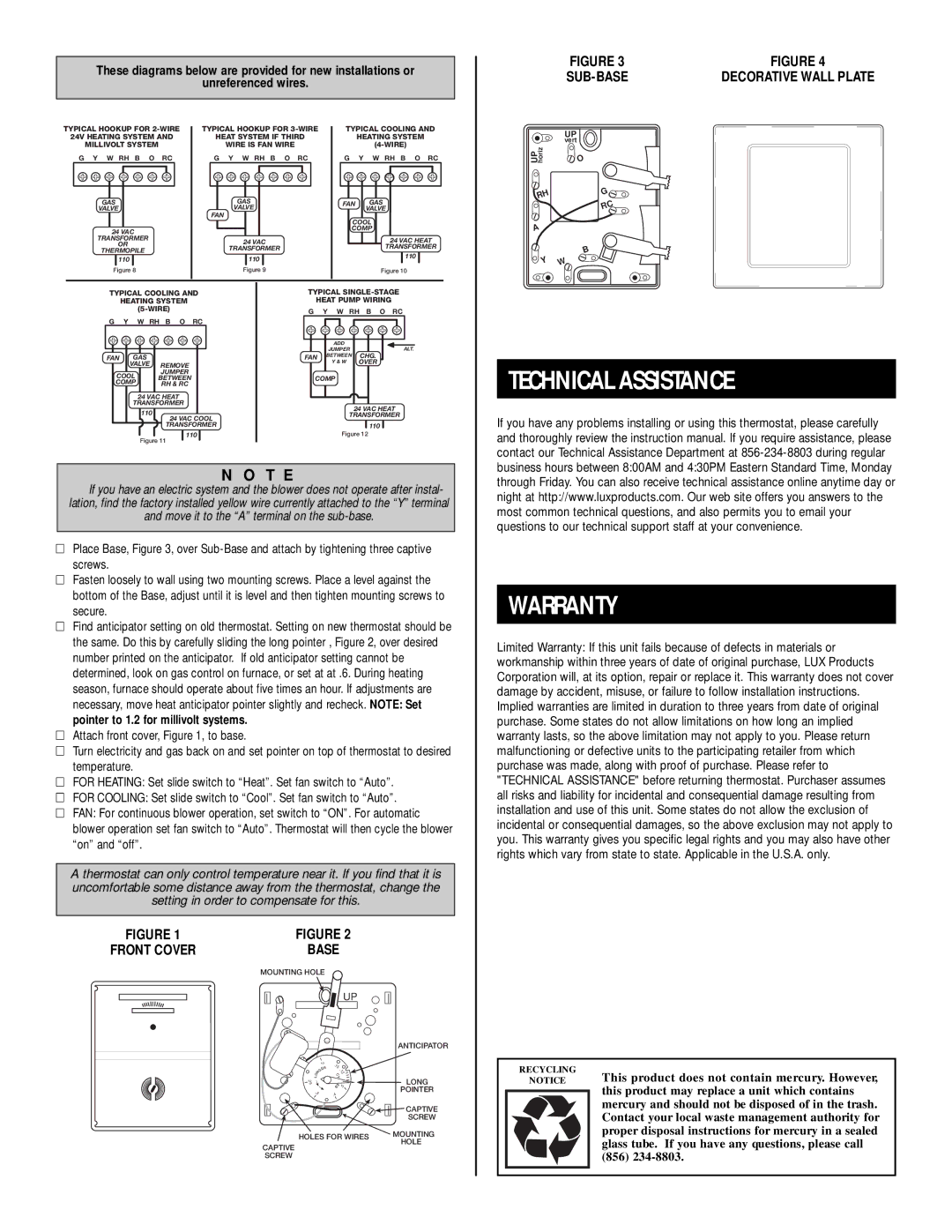
Installation of the Lux Products T40-1143SA is straightforward, making it an appealing option for DIY enthusiasts. The device comes with clear instructions, and its compatibility with conventional wiring systems means that most users can install it without professional assistance.
In summary, the Lux Products T40-1143SA is a feature-rich programmable thermostat that combines ease of use, advanced technologies, and energy efficiency. With its Smart Temp technology, flexible 7-day scheduling, and compatibility with various HVAC systems, this thermostat is a smart choice for anyone looking to enhance comfort while reducing energy costs. Whether used in a home or a commercial space, the T40-1143SA effectively marries functionality with user-friendly design, making it a top contender in the thermostat market.