INSTALLATION AND
OPERATING INSTRUCTIONS
EcoStat® TH10 Heating Only
Mercury FREE Manual Thermostat
52059
LUX PRODUCTS CORPORATION
Mt. Laurel, New Jersey 08054, USA
http://www.luxproducts.com
IM P ORTA N T !
Please read all instructions carefully before beginning installation and save for future reference. Before removing any wiring from your existing thermostat, the wires must be labeled with their terminal designations. Ignore the color of the wires since they may not comply with any standard.
Thank you for your confidence in our product. To obtain the best results from your investment, please read these instructions thoroughly. You should become fully acquainted with this thermostat before installing it for usage. Follow the installation procedures carefully, and one step at a time. This will save you time and minimize the chance of damaging either the thermostat or the systems that it controls. These instructions may contain information beyond that required for your particular installation. Please save these instructions for future reference.
COMPATIBILITY
This mechanical thermostat can be used with most 2-wire, single-stage 24 volt gas, oil, or electric heating systems. It cannot be used with cooling systems, heat pumps, 3 wire zone valves, line voltage (120/240 volt) heating systems, or Millivolt systems. Ask your dealer for other LUX thermostats to control those systems.
FEATURES
• Push Button Back Light | | | | | • Soft Rubber Set Temperature Ring | |
• Glow-In-The-Dark Dial Numbers | | | | | • Large Easy To Use Mode Switches | |
Light Button | | | | | | | |
Mode | | | T | | | | |
| | EA | | | | |
| | F | | | | |
| | | H | | | | |
Switch | O | F | | | 75 | | |
| | 65 | | |
| | 55 | 85 | |
| | | | | Set |
| | | | | |
| | | | | | |
| | | | Mercury | Free | | Temperature |
Ambient | | | 55 | 65 | 75 | 85 | |
| | | |
| | | | |
Room | | | | | | | Set |
Temperature | | | | | | |
| | | | | | Temperature |
| | | | | | |
| | | | | | Selector Ring |
US Patent USP D471,572
SELECTING A LOCATION
On replacement installations, mount the new thermostat in place of the old one unless the conditions listed below suggest otherwise. On new installations, follow the guidelines listed below.
1.Locate the thermostat on an inside wall, about 5 ft. (1.5m) above the floor, and in a room that is used often.
2.Do not locate where air circulation is poor, such as in a corner or an alcove, or behind an open door.
3.Do not install it where there are unusual heating conditions, such as: in direct sunlight; near a lamp, television, radiator, register, or fireplace; near hot water pipes in a wall; near a stove on the other side of a wall.
4.Do not locate in unusual cooling conditions, such as: on a wall separating an unheated room; or in a draft from a stairwell, door, or window.
5.Do not locate in a damp area. This can lead to corrosion that may shorten thermostat life.
6.If painting or construction work has yet to be completed, cover the unit completely or do not install it.
TOOLS REQUIRED | |
• #1 Phillips screwdriver | • #1 Slotted screwdriver |
• Drill with 3/16 in. (4.8mm) bit | • Wire Stripper / Cutter |
NOTE: Review the type of wiring configuration that your system requires, prior to removing your old thermostat or its wiring connections.
REMOVAL OF OLD UNIT
| 1. | Turn OFF the electricity to all heating and cooling components. Do not turn the |
| | electricity back on until all work is completed. |
| 2. | Remove the cover and front portion of your old thermostat to expose the wiring |
OFF | | connections. |
3. | Write down the letters printed near each wire terminal that is used, and the color |
| | of the wire that is connected to it. Using the enclosed labels, attach a label to each |
| | of your wires so that the letter matches the marking on your existing thermostat. |
4. When they are all labeled, carefully remove the wires one at a time, making sure that they do not fall back inside the wall. Do not allow any of the bare wire ends to touch each other, or any parts on the thermostat.
5. Loosen all of the screws on the old thermostat and remove it from the wall.
INSTALLATION
MOUNTING
1.Strip insulation leaving 3/8 in. (9.5mm) bare wire ends and clean off any corrosion.
2.Fill wall opening with non-combustible insulation to prevent drafts from affecting the thermostat.
3.The Wall/Trim Plate is optional, however its usage is recommended.
4.Remove the front trim ring from the thermostat by pulling it straight outwards.
5.If there are no existing mounting holes that are able to be reused, hold the Trim Plate level against the wall with the “UP” markings up, and mark the “outer” two oval mounting holes on the right and left. NOTE: if you are not using the Trim Plate, you can still mark the holes for the thermostat using the two small inner holes on the right and left of the Trim Plate, which line up with the thermostat mounting holes.
6.If you are mounting the base to a soft material like plasterboard, the screws alone may not hold. Drill a 3/16 in. (4.8mm) hole at each screw location, and insert the plastic anchors provided into the wall. If you are mounting to wood or similar substance, the screws may be used alone without the plastic anchors.
7.First, feed the wires through the large middle hole in decorative wall plate (if used) and then through the square lower hole near the bottom of the thermostat’s Sub-Base.
8.Referring to your earlier notes from removing your old thermostat, and the electrical diagrams in this manual, attach the wires to the terminal screws. Make sure bare metal wires do not touch each other. The wire connector screws on the Sub-Base may need to be loosened prior to inserting any wires. When all wiring is complete, ensure that every screw is securely tightened.
© 2008 LUX PRODUCTS CORPORATION . ALL RIGHTS RESERVED
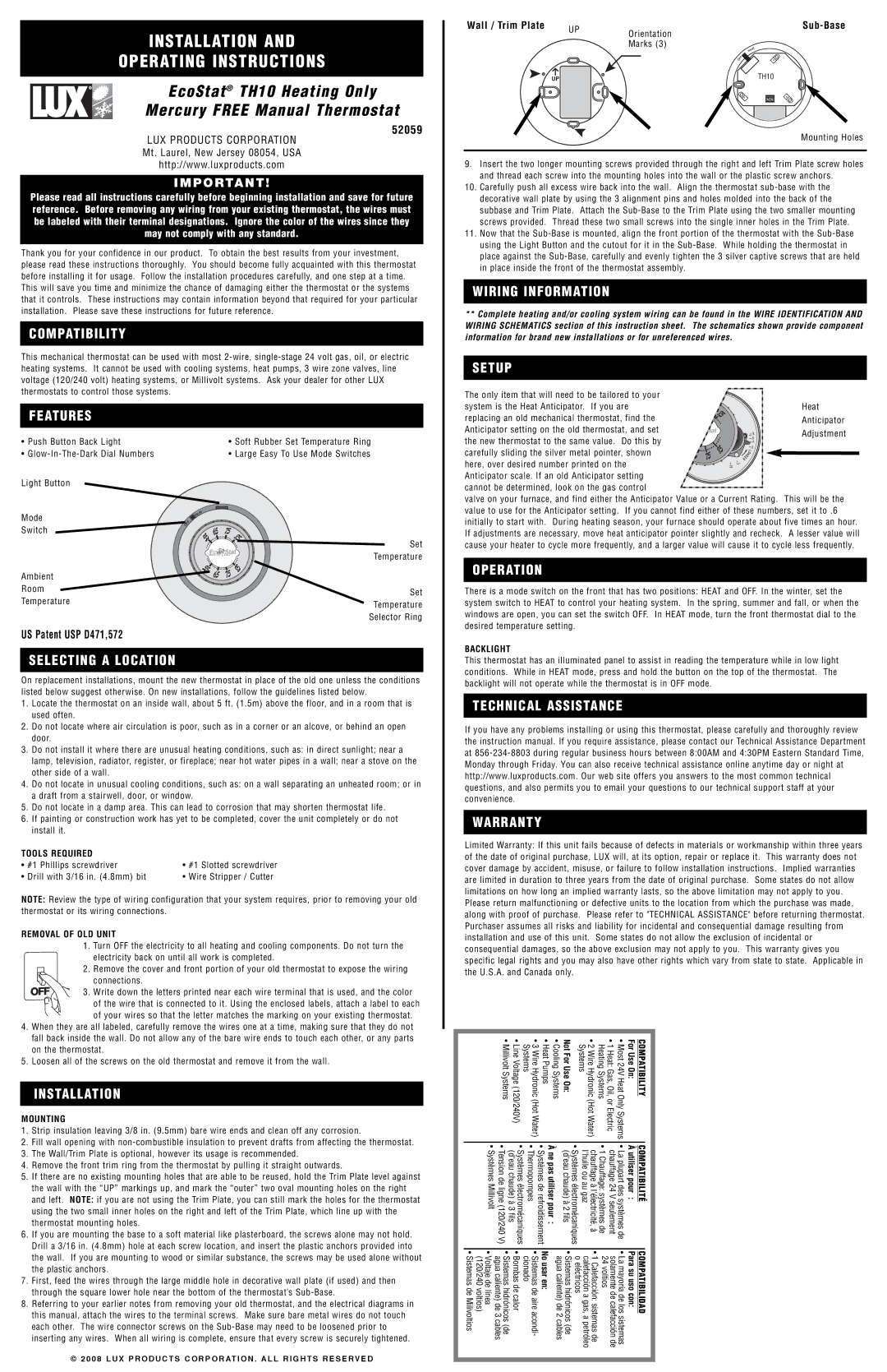
Wall / Trim Plate | UP | Orientation | | | Sub-Base |
| | | |
| | | | |
| | Marks (3) | | | AT |
| | | | | HE |
| | | O | F | F |
| | | |
| | | | |
| UP | | | | TH10 |
Mounting Holes
9.Insert the two longer mounting screws provided through the right and left Trim Plate screw holes and thread each screw into the mounting holes into the wall or the plastic screw anchors.
10.Carefully push all excess wire back into the wall. Align the thermostat sub-base with the decorative wall plate by using the 3 alignment pins and holes molded into the back of the subbase and Trim Plate. Attach the Sub-Base to the Trim Plate using the two smaller mounting screws provided. Thread these two small screws into the single inner holes in the Trim Plate.
11.Now that the Sub-Base is mounted, align the front portion of the thermostat with the Sub-Base using the Light Button and the cutout for it in the Sub-Base. While holding the thermostat in place against the Sub-Base, carefully and evenly tighten the 3 silver captive screws that are held in place inside the front of the thermostat assembly.
WIRING INFORMATION
**Complete heating and/or cooling system wiring can be found in the WIRE IDENTIFICATION AND WIRING SCHEMATICS section of this instruction sheet. The schematics shown provide component information for brand new installations or for unreferenced wires.
SETUP
The only item that will need to be tailored to your | | | | | | | | |
system is the Heat Anticipator. If you are | | 75 | | | | | | Heat |
replacing an old mechanical thermostat, find the | | | | | | | Anticipator |
| | | | | | |
Anticipator setting on the old thermostat, and set | | | | | | | 1.0 | Adjustment |
the new thermostat to the same value. Do this by | | | | | | | .6 |
55 | | | | | | .4 | |
| | | | | | |
| | | | | | L | |
carefully sliding the silver metal pointer, shown | | | 85 | | EG N | | .3 | |
| 75 | | O | | |
here, over desired number printed on the | | | | R | | | |
| | | 8 | . | | | |
| | | | . | 2 | | | |
| | | | 1 | | | | |
Anticipator scale. If an old Anticipator setting cannot be determined, look on the gas control
valve on your furnace, and find either the Anticipator Value or a Current Rating. This will be the value to use for the Anticipator setting. If you cannot find either of these numbers, set it to .6 initially to start with. During heating season, your furnace should operate about five times an hour. If adjustments are necessary, move heat anticipator pointer slightly and recheck. A lesser value will cause your heater to cycle more frequently, and a larger value will cause it to cycle less frequently.
OPERATION
There is a mode switch on the front that has two positions: HEAT and OFF. In the winter, set the system switch to HEAT to control your heating system. In the spring, summer and fall, or when the windows are open, you can set the switch OFF. In HEAT mode, turn the front thermostat dial to the desired temperature setting.
BACKLIGHT
This thermostat has an illuminated panel to assist in reading the temperature while in low light conditions. While in HEAT mode, press and hold the button on the top of the thermostat. The backlight will not operate while the thermostat is in OFF mode.
TECHNICAL ASSISTANCE
If you have any problems installing or using this thermostat, please carefully and thoroughly review the instruction manual. If you require assistance, please contact our Technical Assistance Department at 856-234-8803 during regular business hours between 8:00AM and 4:30PM Eastern Standard Time, Monday through Friday. You can also receive technical assistance online anytime day or night at http://www.luxproducts.com. Our web site offers you answers to the most common technical questions, and also permits you to email your questions to our technical support staff at your convenience.
WARRANTY
Limited Warranty: If this unit fails because of defects in materials or workmanship within three years of the date of original purchase, LUX will, at its option, repair or replace it. This warranty does not cover damage by accident, misuse, or failure to follow installation instructions. Implied warranties are limited in duration to three years from the date of original purchase. Some states do not allow limitations on how long an implied warranty lasts, so the above limitation may not apply to you. Please return malfunctioning or defective units to the location from which the purchase was made, along with proof of purchase. Please refer to "TECHNICAL ASSISTANCE" before returning thermostat. Purchaser assumes all risks and liability for incidental and consequential damage resulting from installation and use of this unit. Some states do not allow the exclusion of incidental or consequential damages, so the above exclusion may not apply to you. This warranty gives you specific legal rights and you may also have other rights which vary from state to state. Applicable in the U.S.A. and Canada only.
| | | • Millivolt Systems | • Line Voltage (120/240V) | Systems | • 3 Wire Hydronic (Hot Water) | • Heat Pumps | • Cooling Systems | Not For Use On: | • 2 Wire Hydronic (Hot Water) Systems | Heating Systems | • 1 Heat: Gas, Oil, or Electric | • Most 24V Heat Only Systems | For Use On: | | COMPATIBILITY | |
| | | | |
| | | | | | | |
| | | | | | | | | | | | | | | |
| | • Systèmes Millivolt | À ne pas utiliser pour : • Systèmes de refroidissement • Thermopompes • Systèmes électromécaniques (d'eau chaude) à 3 fils • Tension de ligne (120/240 V) | (d'eau chaude) à 2 fils | • Systèmes électromécaniques | l'huile ou au gaz | chauffage à l'électricité, à | • 1 Chauffage: systèmes de | chauffage 24 V seulement | • La plupart des systèmes de | À utiliser pour : | | COMPATIBILITÉ | |
| | | |
| | |
| | | | | | | | | | | | | | | | | | | |
| | • Voltaje de línea (120/240 voltios) • Sistemas de Milivoltios | • Sistemas hidrónicos (de agua caliente) de 3 cables | • Bombas de calor | cionado | • Sistemas de aire acondi- | No usar en: | agua caliente) de 2 cables | • Sistemas hidrónicos (de | o eléctricos | calefacción a gas, a petróleo | • 1 Calefacción: sistemas de | solamente de calefacción de 24 voltios | • La mayoría de los sistemas | Para su uso con: | | COMPATIBILIDAD | |
| | | |
| | | | | | |
| | | | | | | | | | | | | | | | | | | | |
| | | | | | | | | | | | | | | | | | | | |