22ME601B, 19ME601B specifications
The Magnavox 22ME601B and 19ME601B are part of a line of televisions developed to provide quality viewing experiences combined with user-friendly features. Both models cater to varying size preferences and come equipped with innovative technologies that enhance their performance.The 22ME601B boasts a 22-inch screen size, making it an ideal choice for smaller rooms, while the 19ME601B, with its 19-inch screen, serves as a perfect option for even more compact spaces. These televisions are designed with a sleek aesthetic, fitting seamlessly into any decor.
A standout feature of the Magnavox 22ME601B and 19ME601B models is their LED backlighting technology. This feature allows for brighter images with improved color accuracy, leading to an enhanced viewing experience. The LED-backlit display contributes to energy efficiency, ensuring that users enjoy their favorite content without a substantial increase in energy consumption.
Both models incorporate a resolution of 720p, effectively delivering sharp images with clear details. The clarity offered by these televisions makes them an excellent choice for watching movies, sports, or television shows. Furthermore, the aspect ratio is 16:9, which aligns with modern media formats, ensuring that users can enjoy widescreen content without any distortion.
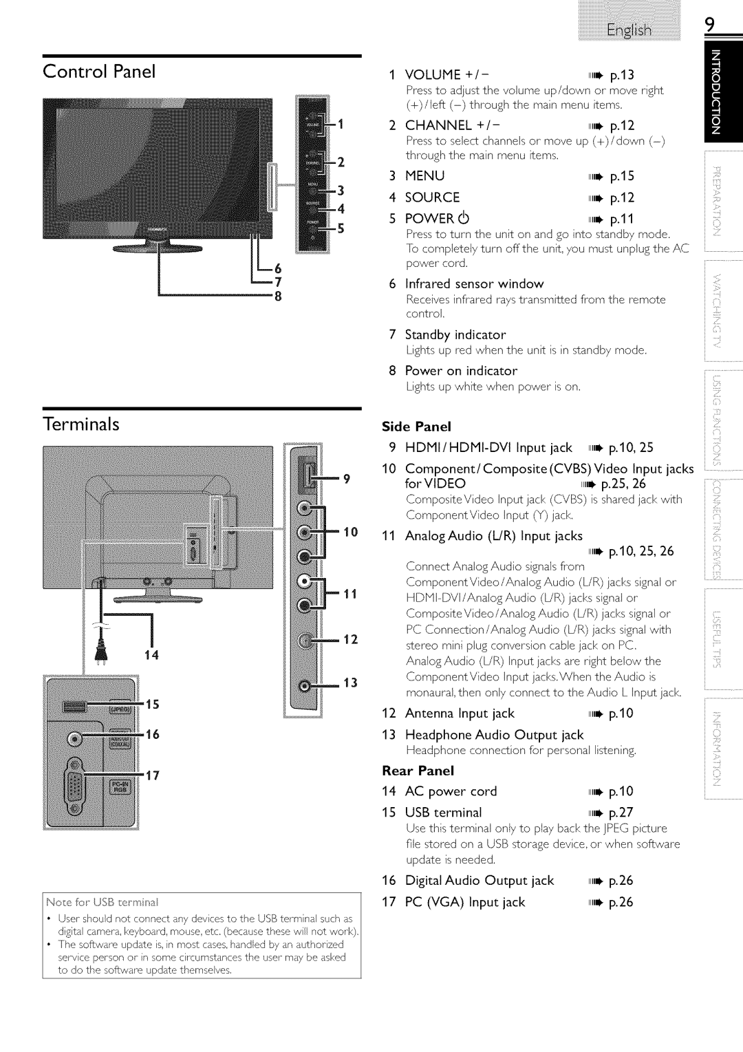
The user interface is designed for ease of use, with intuitive controls and an accessible remote. Connectivity options also play a crucial role, as both models include multiple HDMI ports, enabling users to connect various devices like gaming consoles, DVD players, or streaming devices. Additionally, USB ports facilitate easy access to media files, allowing users to view their photos or videos directly on the television.
Sound quality is not overlooked in these models. Built-in speakers provide decent audio output, although enthusiasts may choose to connect external sound systems for a more immersive experience.
In summary, the Magnavox 22ME601B and 19ME601B offer compact yet powerful television options featuring LED technology, 720p resolution, and convenient connectivity options. Their blend of performance, design, and functionality makes them appealing choices for anyone looking to enhance their home entertainment setup.

