Manuals
/
Majestic Appliances
/
Household Appliance
/
Gas Heater
Majestic Appliances
UVS36RN Hard Direct Wire Hook-Up, EB1 Receptacle Hook-Up, Remote Wall Switch
Models:
UVS36RP
UVS33RN
UVS36RN
UVS33RP
1
9
24
24
Download
24 pages
32.3 Kb
6
7
8
9
10
11
12
13
Troubleshooting
Flame Characteristics
Install
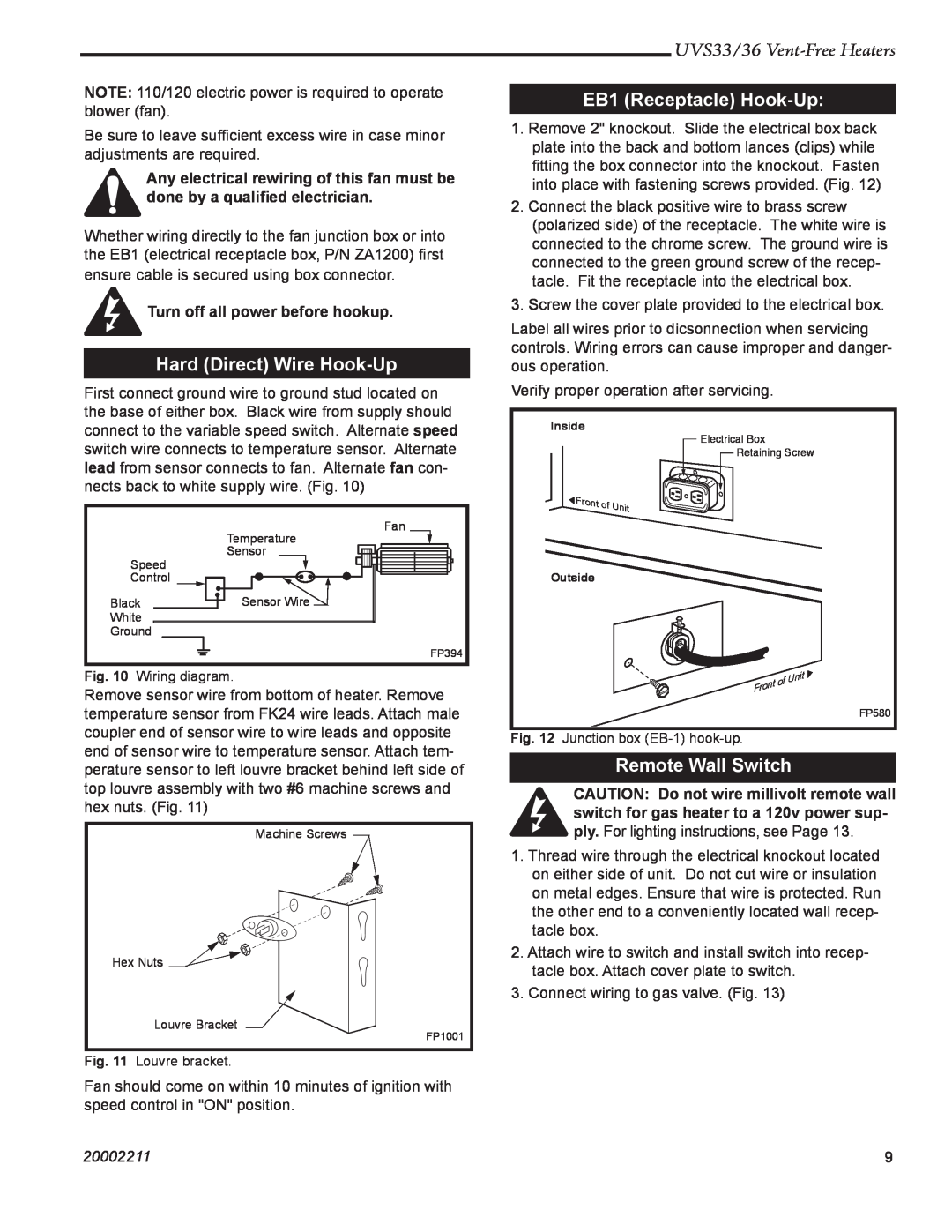
Hard Direct Wire Hook-Up
Warranty
Dimension
Maintenance
Optional Accessories
Flame Adjustment
Safety
Page 9
Image 9
Page 8
Page 10
Page 9
Image 9
Page 8
Page 10
Contents
PLEASE READ THIS MANUAL
BEFORE INSTALLING AND USING HEATERS
Homeowners Installation and
Vent-FreeGas Room Heaters
Table of Contents
UVS33/36 Vent-FreeHeaters
20002211
California Health & Safety Code Sec
Installation & Operating Instructions
UVS33/36 Vent-FreeHeaters
20002211
Fireplace Dimensions
Fireplace Dimensions
UVS33/36 Vent-FreeHeaters
20002211
Description
Safety Devices
Orifice Conversion Instructions
Clearance to Combustibles
Hearth Extension
Mantels
Planning
Mounting the Heater
Insulating for Cold Climates
Framing
Gas Specifications
UVS33/36 Vent-FreeHeaters
UVS33 / UVS36 Certified To ANSI Z 21.11.2a-2003
Electrical Connection
Unvented Room Heaters
Gas Inlet and Manifold Pressures
Remote Wall Switch
Hard Direct Wire Hook-Up
EB1 Receptacle Hook-Up
UVS33/36 Vent-FreeHeaters
Finishing
Alternate Switch Location
UVS33/36 Vent-FreeHeaters
20002211
Operating Instructions
Log Installation UVS33
Top Louvre Grille Removal
Window Frame Removal
Ember Material Placement
Log Installation UVS36
Flame Adjustment
Lava Rock
UVS33/36 Vent-FreeHeaters
Flame Characteristics
counterclockwise
Turn clockwise
To Turn Off Gas to Heater
FOR YOUR SAFETY READ BEFORE LIGHTING
Lighting and Operating Instructions
Lighting Instructions
Honeywell
Troubleshooting
UVS33/36 Vent-FreeHeaters
START
Cleaning the Standing Pilot Control System
Maintenance
UVS33/36 Vent-FreeHeaters
20002211
UVS33/36 Vent-FreeHeaters
UVS33/36 Vent Free Gas Room Heater
Description
UVS33
UVS33/36 Vent Free Gas Room Heater continued
UVS33/36 Vent-FreeHeaters
20002211
Remote Controls
Optional Accessories
Fan Kits
Outside Air Termination
Glass/Catalyst Kit
Decorative Frame Trims
UVS33/36 Vent-FreeHeaters
20002211
Installation
Decorative Bay Window
UVS33/36 Vent-FreeHeaters
20002211
20002211
UVS33/36 Vent-FreeHeaters
PRODUCT COVERED BY THIS WARRANTY
LIMITED LIFETIME WARRANTY
IF WARRANTY SERVICE IS NEEDED…
2DO NOT ATTEMPT TO DO ANY SERVICE WORK YOURSELF
CFM Corporation
CFM Corporation
Top
Page
Image
Contents