P 13/ 14
 Maintenance program
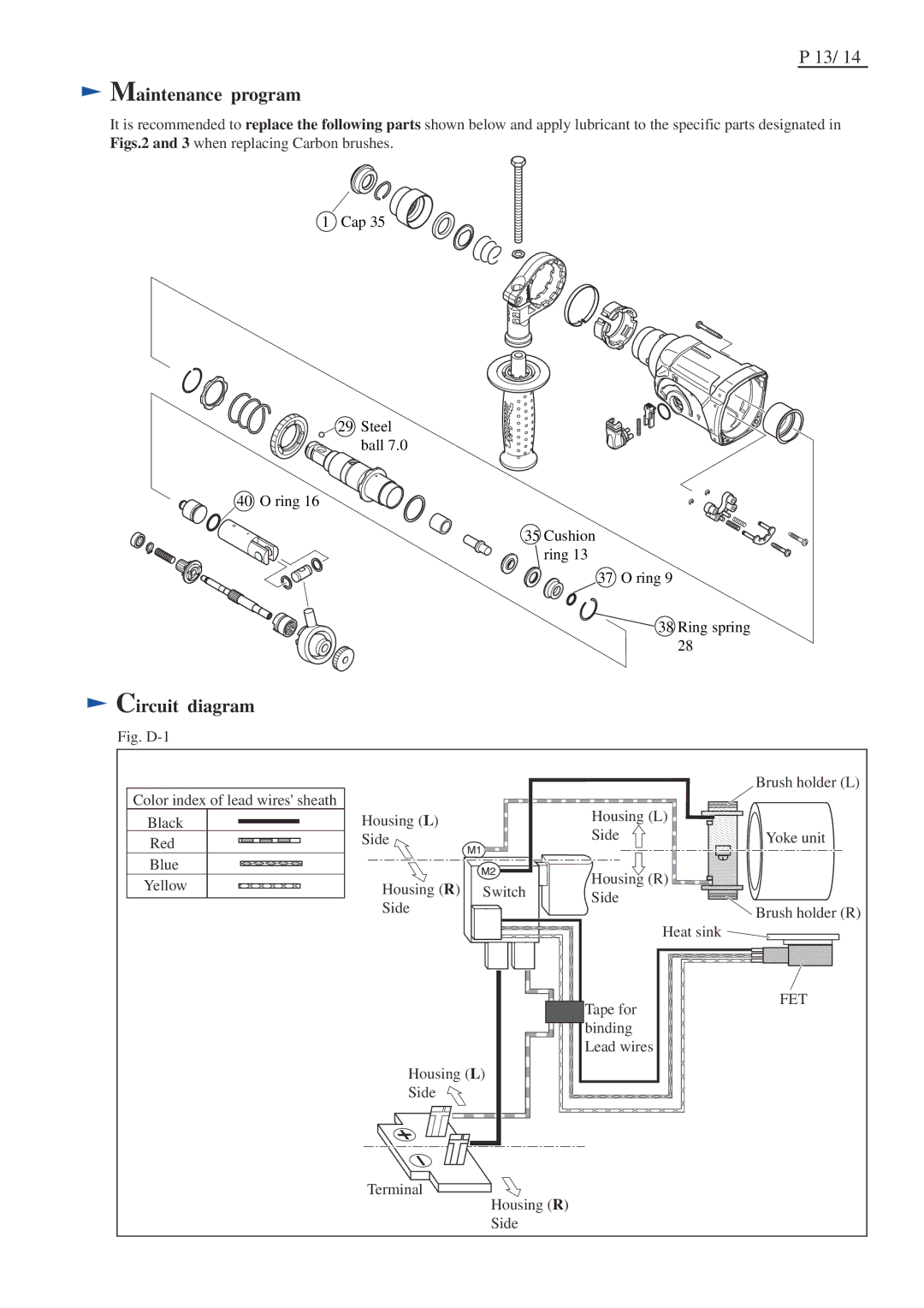
It is recommended to replace the following parts shown below and apply lubricant to the specific parts designated in Figs.2 and 3 when replacing Carbon brushes.
1 Cap 35
![]() 29 Steel ball 7.0
29 Steel ball 7.0
40 O ring 16
35 Cushion
![]() ring 13
ring 13
37 O ring 9
![]() 38 Ring spring 28
38 Ring spring 28
 Circuit diagram
Fig. |
|
|
|
|
|
|
|
| Brush holder (L) |
Color index of lead wires' sheath |
|
| Housing (L) |
|
Black | Housing (L) |
|
| |
Red | Side |
| Side | Yoke unit |
Blue |
|
| Housing (R) |
|
Yellow | Housing (R) | Switch |
| |
Side |
| |||
| Side |
| Brush holder (R) | |
|
|
| ||
|
|
|
| |
|
|
| Heat sink |
|
|
|
| Tape for | FET |
|
|
|
| |
|
|
| binding |
|
|
|
| Lead wires |
|
| Housing (L) |
|
| |
| Side |
|
|
|
| Terminal | Housing (R) |
|
|
|
|
|
| |
|
| Side |
|
|
