P 8/ 10
 Repair
[3] DISASSEMBLY/ASSEMBLY
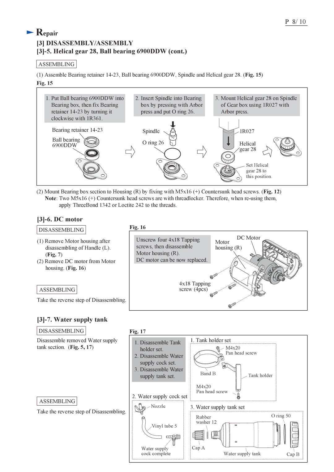
[3]-5. Helical gear 28, Ball bearing 6900DDW (cont.)
ASSEMBLING
(1)Assemble Bearing retainer
Fig. 15
1.Put Ball bearing 6900DDW into Bearing box, then fix Bearing retainer
Bearing retainer
Ball bearing 6900DDW
2.Insert Spindle into Bearing box by pressing with Arbor press and put O ring 26.
Spindle
O ring 26
3.Mount Helical gear 28 on Spindle of Gear box using 1R027 with Arbor press.
![]() 1R027
1R027
Helical
![]() gear 28
gear 28
Set Helical gear 28 to this position.
(2)Mount Bearing box section to Housing (R) by fixing with M5x16 (+) Countersunk head screws. (Fig. 12) Note: Two M5x16 (+) Countersunk head screws are with threadlocker. Therefore, when
apply ThreeBond 1342 or Loctite 242 to the threads.
[3]-6. DC motor
DISASSEMBLING
Fig. 16
(1)Remove Motor housing after disassembling of Handle (L). (Fig. 7)
(2)Remove DC motor from Motor housing. (Fig. 16)
ASSEMBLING
Take the reverse step of Disassembling.
Unscrew four 4x18 Tapping screws, then disassemble Motor housing (R).
DC motor can be now replaced.
4x18 Tapping screw (4pcs)
DC Motor
Motor housing (R)
[3]-7. Water supply tank
DISASSEMBLING
Disassemble removed Water supply tank section. (Fig. 5, 17)
ASSEMBLING
Take the reverse step of Disassembling.
Fig. 17
1. Disassemble Tank | 1. Tank holder set |
|
| |
M4x20 |
|
| ||
holder set. |
|
| ||
2. Disassemble Water | Pan head screw |
| ||
|
|
| ||
supply cock set. |
|
|
| |
3. Disassemble Water | Band B | Tank holder | ||
supply tank set. | ||||
| ||||
| M4x20 |
|
| |
2. Water supply cock set | Pan head screw |
|
| |
|
|
| ||
Nozzle | 3. Water supply tank set |
|
| |
| Rubber |
| O ring 50 | |
Vinyl tube 5 | washer 12 |
|
| |
|
|
| ||
Water supply | Cap A |
|
| |
cock complete | Water supply tank | Cap B | ||