P 13 /17
![]() Wiring diagram
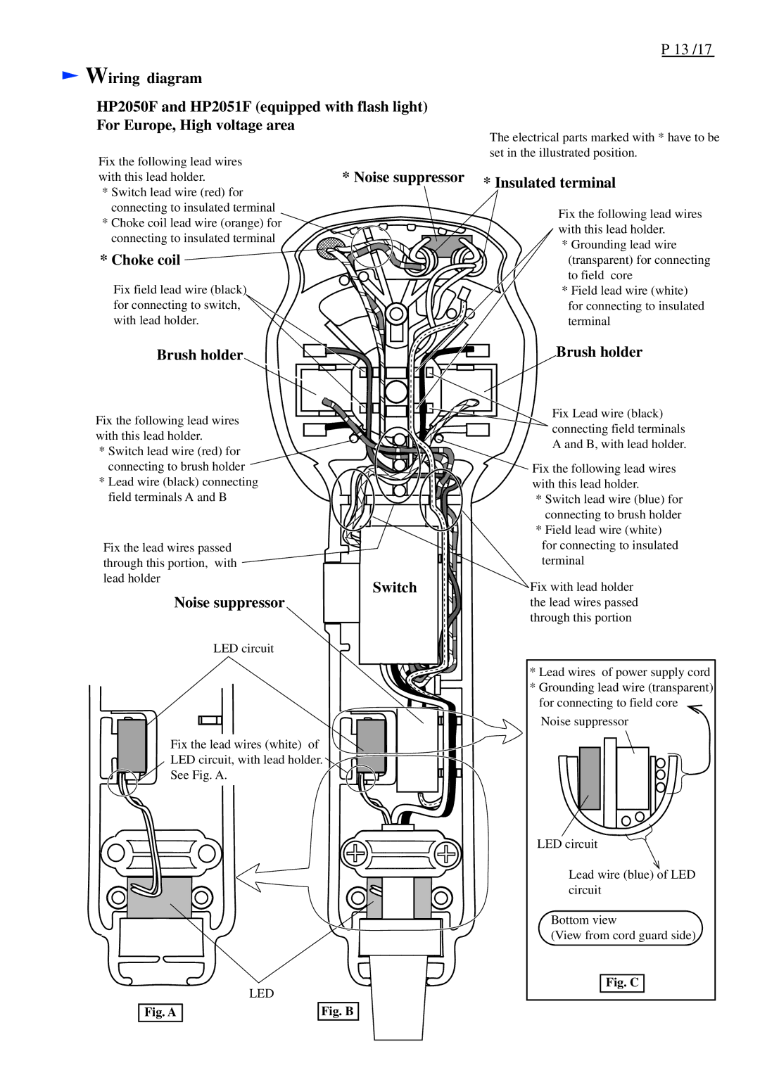
Wiring diagram
HP2050F and HP2051F (equipped with flash light) For Europe, High voltage area
Fix the following lead wires | * Noise suppressor |
with this lead holder. |
*Switch lead wire (red) for connecting to insulated terminal
* Choke coil lead wire (orange) for connecting to insulated terminal
* Choke coil 

Fix field lead wire (black) for connecting to switch, with lead holder.
Brush holder
Fix the following lead wires with this lead holder.
* Switch lead wire (red) for connecting to brush holder
* Lead wire (black) connecting field terminals A and B
Fix the lead wires passed through this portion, with lead holder
Switch
Noise suppressor
LED circuit
Fix the lead wires (white) of
LED circuit, with lead holder.
See Fig. A.
| LED | |
Fig. A |
| Fig. B |
The electrical parts marked with * have to be set in the illustrated position.
* Insulated terminal
Fix the following lead wires with this lead holder.
*Grounding lead wire (transparent) for connecting to field core
*Field lead wire (white)
for connecting to insulated terminal
Brush holder
Fix Lead wire (black) connecting field terminals A and B, with lead holder.
Fix the following lead wires with this lead holder.
*Switch lead wire (blue) for connecting to brush holder
*Field lead wire (white)
for connecting to insulated terminal
Fix with lead holder the lead wires passed through this portion
*Lead wires of power supply cord
*Grounding lead wire (transparent) for connecting to field core Noise suppressor
LED circuit
Lead wire (blue) of LED circuit
Bottom view
(View from cord guard side)