INSTALLATION AND BREAK-IN PROCEDURES (cont'd)
GROUNDING INSTRUCTION (cont'd)
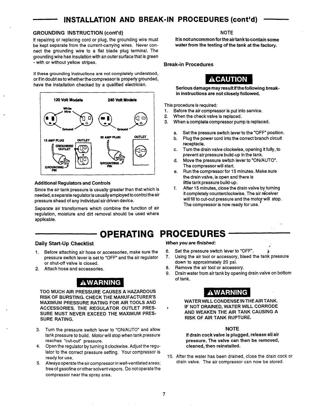
If repairing or replacing cord or plug, the grounding wire must be kept separate from the
-with or without yellow stripes.
If these grounding instructions are not completely understood, or if indoubt asto whetherthecompressoris properlygrounded, have the installation checked by a qualified electrician.
120 Volt Modete | 240 b i t Models |
Additional Regulators and Controls
Since the air tank pressure is usually greater than that which is needed, aseparate regulatorisusuallyemployedtocontrolthe air pressure ahead of any individualair driven device.
Separate air transformers which combine the function of air regulation, moisture and dirt removal should be used where applicable.
NOTE
Itis notuncommon for the airtank to contain some water from the testing of the tank at the factory.
Break4n Procedures
Serious damage may result ifthefollowing break- in instructions are notclosely followed.
This procedure is required:
1.Before the air compressor is put into service.
2.When the checkvalve is replaced.
3.When a complete compressor pump is replaced.
a.Set the pressure switch lever to the ''OFF'' position.
b.Plug the power cord into the correct branch circuit receptacle.
c.Turn the drain valve clockwise, opening itfully, to prevent air pressure
d.Move the pressure switch lever to "OWAUTO". The compressor will start.
e.Run the compressor for 15 minutes. Make sure the drain valve, is open and there is
little tank
f.After 15 minutes, close the drain valve by turning it completely counterclockwise.The air rdceiver will fill to
OPERATING PROCEDURES
Daily Start-up Checklist
1.Before attaching air hose or accessories, make sure the
pressure switch lever is set to "OFF" and the air regulator or
2.Attach hose and accessories.
TOO MUCH AIR PRESSURE CAUSES A HAZARDOUS RISK OF BURSTING. CHECK THE MANUFACTURER'S MAXIMUM PRESSURE RATING FOR AIR TOOLS AND ACCESSORIES. THE REGULATOR OUTLET PRES- SURE MUST NEVER EXCEED THE MAXIMUM PRES- SURE RATING.
When you are finished:
| # |
6. Set the pressure switch lever to "OFF. | J. |
7.Using the air tool or accessory, bleed the tank pressure down to approximately 20 psi.
8.Remove the air tool or accessory.
9.Drain water from air tank by opening drain valve on bottom of tank.
WATER WILL CONDENSE INTHE AIRTANK.
IF NOT DRAINED, WATER WILL CORRODE
AND WEAKEN THE AIR TANK CAUSING A
RISK OF AIR TANK RUPTURE.
3.Turn the pressure switch lever to "ON/AUTO and allow tank pressure to build. Motor will stop when tank pressure reaches
4.Open the regulator by turning it clockwise. Adjust the regu-
lator to the correct pressure setting. Your compressor is ready for use.
5.Alwaysoperate the aircompressorin
NOTE
If drain cockvalve is plugged, release all air pressure. The valve can then be removed, cleaned, then reinstalled.
10.After the water has been drained, close the drain cock or drain valve. The air compressor can now be stored.
7
