Q-DUAL WATER LEVEL PROBE (WLP)
Installation Instructions for Kit 76-0293-3
Ice machines which presently have the
1.Place toggle switch in OFF position, move the switch back to ICE for 40 seconds to remove the water from the sump trough, and then turn the switch back to OFF.
2.Disconnect power to the ice machine at the main disconnect.
3.Remove the
4.Disconnect and remove the water pump.
5.Mark WLP relocation point:
A.Use the template on the next page to mark the correct position for the new WLP. **Prior to serial number, 020200000, the template is not needed - holes have been drilled.**
B.Align water pump holes with template and then place two marks on the back wall to the right of the water pump.
6.A refrigerant line may be located directly behind the previously marked location. Use a drill stop and drill two holes at the marked locations. The top hole will be a 1/8” hole; the bottom hole will be 1/2” in diameter.
![]() WARNING
WARNING
Use a suitable means to capture, contain, and remove all metal shavings produced during the drilling process.
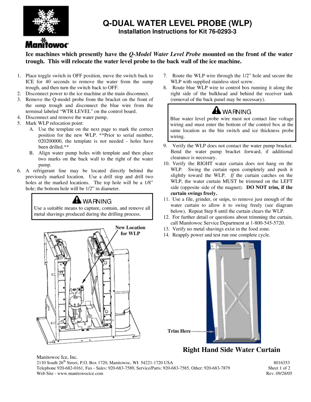
New Location
for WLP
7.Route the WLP wire through the 1/2” hole and secure the WLP with supplied stainless steel screw.
8.Route blue WLP wire to control box running it along the right side of the bulkhead and behind the receiver tank (removal of the back panel may be necessary).
![]() WARNING
WARNING
Blue water level probe wire must not contact line voltage wiring and must enter the bottom of the control box at the same location as the bin switch and ice thickness probe wiring.
9.Verify the WLP does not contact the water pump bracket. Bend the water pump bracket forward, if additional clearance is necessary.
10.Verify the RIGHT water curtain does not hang on the WLP. Swing the curtain open completely and push it slightly toward the WLP. If the curtain catches on the WLP, the water curtain MUST be trimmed on the LEFT side (opposite side of the magnet). DO NOT trim, if the curtain swings freely.
11.Use a file, grinder, or snips, to remove just enough of the water curtain to allow it to swing freely (see diagram below). Repeat Step 8 until the curtain clears the WLP.
12.For further detail or questions about trimming the curtain, call Manitowoc Service Department at
13.Verify no metal shavings exist in the food zone.
14.Reapply power and test run one complete cycle.
Trim Here 
Right Hand Side Water Curtain
Manitowoc Ice, Inc.
2110 South 26th Street, P.O. Box 1720, Manitowoc, WI | 8016353 |
Telephone | Sheet 1 of 2 |
Web Site - www.manitowocice.com | Rev. 09/28/05 |