NBE100 User's Manual
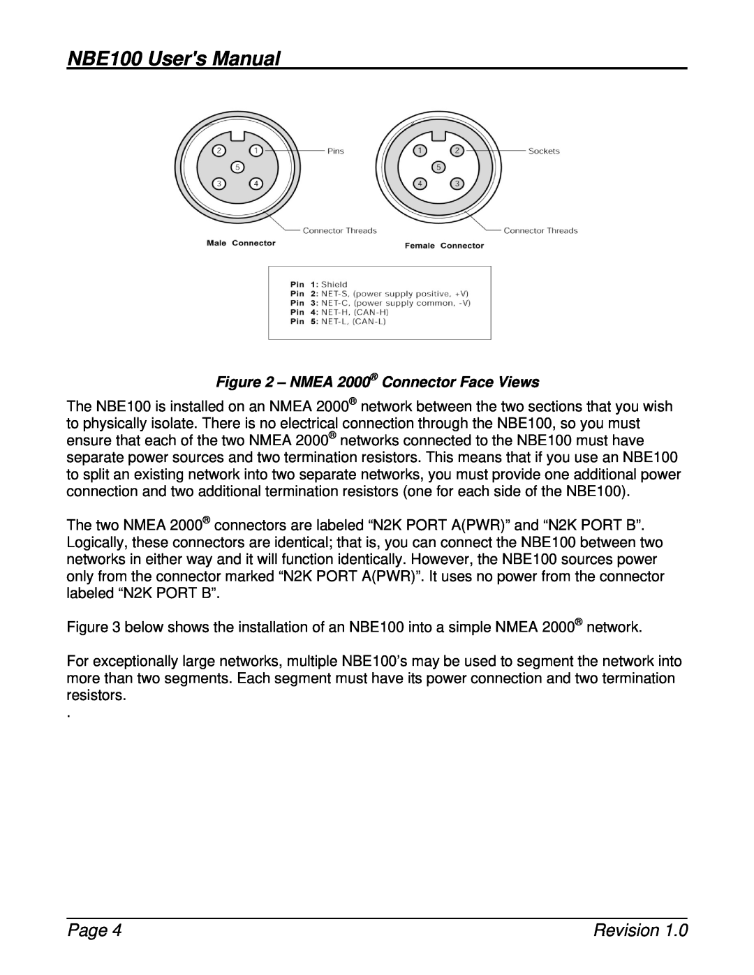
Figure 2 – NMEA 2000® Connector Face Views
The NBE100 is installed on an NMEA 2000® network between the two sections that you wish to physically isolate. There is no electrical connection through the NBE100, so you must ensure that each of the two NMEA 2000® networks connected to the NBE100 must have separate power sources and two termination resistors. This means that if you use an NBE100 to split an existing network into two separate networks, you must provide one additional power connection and two additional termination resistors (one for each side of the NBE100).
The two NMEA 2000® connectors are labeled “N2K PORT A(PWR)” and “N2K PORT B”. Logically, these connectors are identical; that is, you can connect the NBE100 between two networks in either way and it will function identically. However, the NBE100 sources power only from the connector marked “N2K PORT A(PWR)”. It uses no power from the connector labeled “N2K PORT B”.
Figure 3 below shows the installation of an NBE100 into a simple NMEA 2000® network.
For exceptionally large networks, multiple NBE100’s may be used to segment the network into more than two segments. Each segment must have its power connection and two termination resistors.
.
Page 4 | Revision 1.0 |