Manuals
/
Maretron
/
Computer Equipment
/
Switch
Maretron
SIM100 Switch Connections, NMEA 2000 Connector Face Views, Pin # Signal Name, Page
Models:
SIM100
1
8
17
17
Download
17 pages
13.36 Kb
5
6
7
8
9
10
11
12
Troubleshooting
Specifications
Install
Pin # Signal Name
SIM100 Switch Indicator Module
Connecting the SIM100
Warranty
Configuring the SIM100
1.2 SIM100 Features
Page 8
Image 8
Page 7
Page 9
Page 8
Image 8
Page 7
Page 9
Contents
Revision
Page
Revision Copyright 2008 Maretron, LLP All Rights Reserved
Maretron, LLP 9014 N. 23rd Ave #10
Revision History
SIM100 Users Manual
Page
Revision
Table of Appendices
Table of Contents
Table of Figures
Page
1.1 Firmware Revision
1.2 SIM100 Features
1 Introduction
2 Installation
1.3 SIM100 Accessories
1.4 Quick Install
2.1 Unpacking the Box
2.4 Connecting the SIM100
2.3 Mounting the SIM100
2.4.1 NMEA 2000 Connection
Figure 1 - Mounting the SIM100
2.4.2 Switch Connections
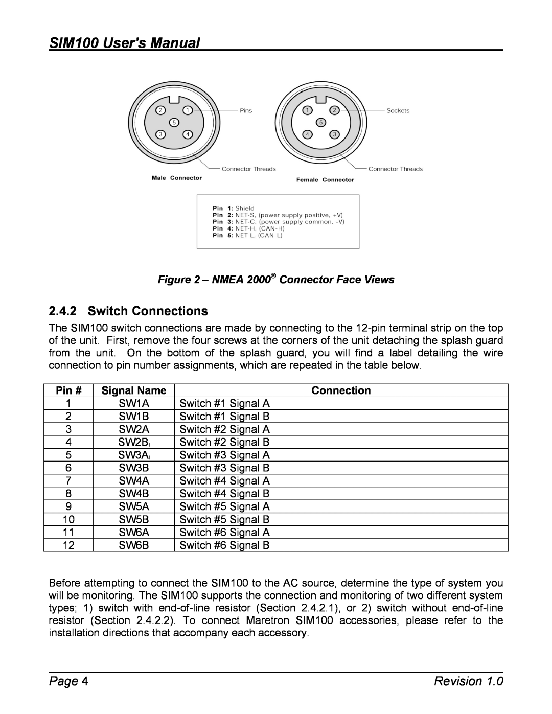
Figure 2 - NMEA 2000 Connector Face Views
Pin # Signal Name
Connection
2.4.2.1 Switch With End of Line Resistor
Figure 3 - Switch With End of Line Resistor Connection Diagram
2.4.2.2 Switch Without End of Line Resistor
Figure 4 - Switch Without End of Line Resistor Connection Diagram
2.5 Configuring the SIM100
2.4.3 Checking Connections
2.5.1 Device Instance
2.5.2 Channel #1 Mode 2.5.3 Channel #2 Mode 2.5.4 Channel #3 Mode
3 Maintenance
4 Troubleshooting
2.5.8 Advanced Configuration…
2.5.9 NMEA 2000 PGN Enable/Disable
Revision
5 Technical Specifications
Specifications
Certifications
NMEA 2000 Parameter Group Numbers PGNs
6 Technical Support
support@maretron.com
7 Installation Template
Figure 5 - Mounting Surface Template
8 Maretron 2 Year Limited Warranty
Warranty Return Procedure
PGN 127501 - Binary Switch Bank Status
Appendix A - NMEA 2000 Interfacing
SIM100 NMEA 2000 Periodic Data Transmitted PGNs
Appendix A - NMEA 2000 Interfacing
Top
Page
Image
Contents