Manuals
/
Maretron
/
Computer Equipment
/
Switch
Maretron
installation instructions
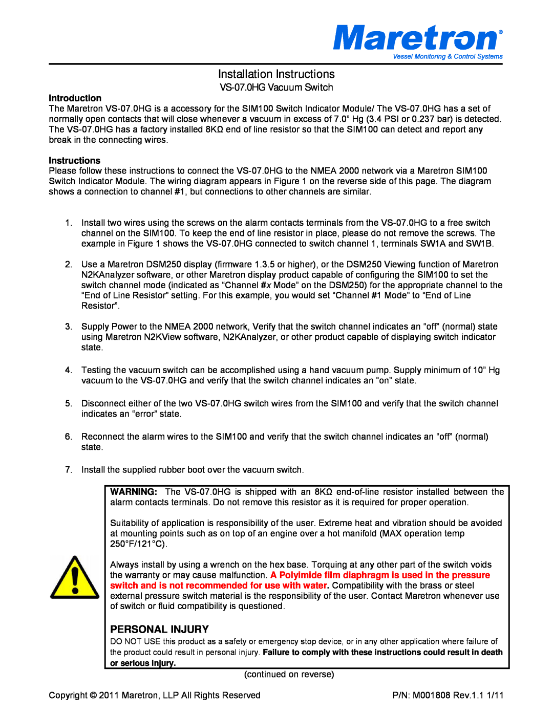
Installation Instructions, VS-07.0HG Vacuum Switch
Models:
VS-07.0HG
1
1
2
2
Download
2 pages
46.77 Kb
1
2
Specs
Install
Page 1
Image 1
Page 1
Page 2
Page 1
Image 1
Page 1
Page 2
Contents
VS-07.0HG Vacuum Switch
Installation Instructions
Introduction
Instructions
Maretron, LLP 9014 N. 23rd Ave #10 Phoenix, AZ
Device Specifications
Parameter
Value
Top
Page
Image
Contents