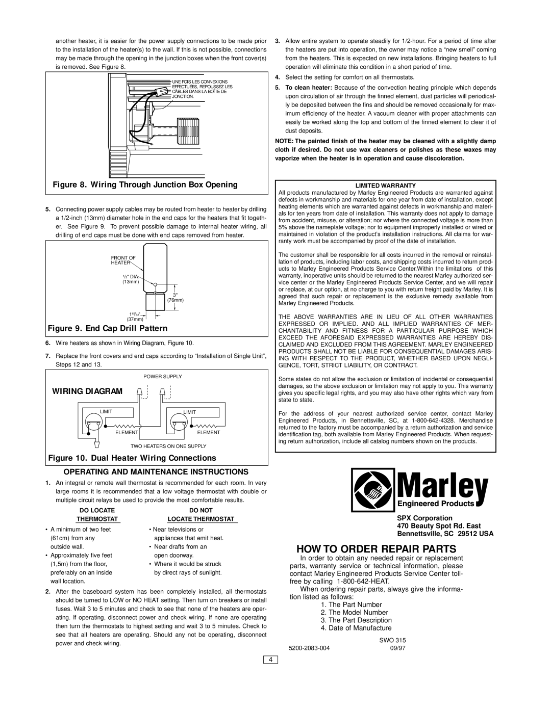
another heater, it is easier for the power supply connections to be made prior
to the installation of the heater(s) to the wall. If this is not possible, connections may be made through the opening in the junction boxes when the front cover(s)
is removed. See Figure 8.
UNE FOIS LES CONNEXIONS
EFFECTUÉES, REPOUSSEZ LES
CÂBLES DANS LA BOÎTE DE
JONCTION.
Figure 8. Wiring Through Junction Box Opening
5.Connecting power supply cables may be routed from heater to heater by drilling
a 1/2-inch (13mm) diameter hole in the end caps for the heaters that fit togeth- er. See Figure 9. To prevent possible damage to internal heater wiring, all drilling of end caps must be done with end caps removed from heater.
FRONT OF
HEATER 
1/2" DIA. (13mm)
3"
(76mm)
115/32" 
(37mm)
Figure 9. End Cap Drill Pattern
6.Wire heaters as shown in Wiring Diagram, Figure 10.
7.Replace the front covers and end caps according to “Installation of Single Unit”, Steps 12 and 13.
POWER SUPPLY
WIRING DIAGRAM
TWO HEATERS ON ONE SUPPLY
Figure 10. Dual Heater Wiring Connections
OPERATING AND MAINTENANCE INSTRUCTIONS
1.An integral or remote wall thermostat is recommended for each room. In very large rooms it is recommended that a low voltage thermostat with double or multiple circuit relays be used to provide the most comfortable results.
| | DO LOCATE | | DO NOT |
| | THERMOSTAT | | LOCATE THERMOSTAT |
• | A minimum of two feet | • Near televisions or |
| (61cm) from any | appliances that emit heat. |
| outside wall. | • Near drafts from an |
• | Approximately five feet | open doorway. |
| (1,5m) from the floor, | • Where it would be struck |
| preferably on an inside | by direct rays of sunlight. |
| wall location. | | |
2.After the baseboard system has been completely installed, all thermostats should be turned to LOW or NO HEAT setting. Then turn on breakers or install fuses. Wait 3 to 5 minutes and check to see that none of the heaters are oper- ating. If operating, disconnect power and check wiring. If none are operating then turn the thermostats to highest setting and wait 3 to 5 minutes. Check to see that all heaters are operating. Should any not be operating, disconnect power and check wiring.
3.Allow entire system to operate steadily for 1/2-hour. For a period of time after the heaters are put into operation, the owner may notice a “new smell” coming from the heaters. This is expected on new installations. Bringing heaters to full operation will eliminate this condition in a short period of time.
4.Select the setting for comfort on all thermostats.
5.To clean heater: Because of the convection heating principle which depends upon circulation of air through the finned element, dust particles will periodical-
ly be deposited between the fins and should be removed occasionally for max- imum efficiency of the heater. A vacuum cleaner with proper attachments can easily be worked along the top and bottom of the finned element to clear it of dust deposits.
NOTE: The painted finish of the heater may be cleaned with a slightly damp cloth if desired. Do not use wax cleaners or polishes as these waxes may vaporize when the heater is in operation and cause discoloration.
LIMITED WARRANTY
All products manufactured by Marley Engineered Products are warranted against defects in workmanship and materials for one year from date of installation, except heating elements which are warranted against defects in workmanship and materi- als for ten years from date of installation. This warranty does not apply to damage from accident, misuse, or alteration; nor where the connected voltage is more than 5% above the nameplate voltage; nor to equipment improperly installed or wired or maintained in violation of the product’s installation instructions. All claims for war- ranty work must be accompanied by proof of the date of installation.
The customer shall be responsible for all costs incurred in the removal or reinstal- lation of products, including labor costs, and shipping costs incurred to return prod- ucts to Marley Engineered Products Service Center.Within the limitations of this warranty, inoperative units should be returned to the nearest Marley authorized ser- vice center or the Marley Engineered Products Service Center, and we will repair
or replace, at our option, at no charge to you with return freight paid by Marley. It is agreed that such repair or replacement is the exclusive remedy available from Marley Engineered Products.
THE ABOVE WARRANTIES ARE IN LIEU OF ALL OTHER WARRANTIES
EXPRESSED OR IMPLIED. AND ALL IMPLIED WARRANTIES OF MER-
CHANTABILITY AND FITNESS FOR A PARTICULAR PURPOSE WHICH
EXCEED THE AFORESAID EXPRESSED WARRANTIES ARE HEREBY DIS-
CLAIMED AND EXCLUDED FROM THIS AGREEMENT. MARLEY ENGINEERED
PRODUCTS SHALL NOT BE LIABLE FOR CONSEQUENTIAL DAMAGES ARIS-
ING WITH RESPECT TO THE PRODUCT, WHETHER BASED UPON NEGLI-
GENCE, TORT, STRICT LIABILITY, OR CONTRACT.
Some states do not allow the exclusion or limitation of incidental or consequential damages, so the above exclusion or limitation may not apply to you. This warranty gives you specific legal rights, and you may also have other rights which vary from state to state.
For the address of your nearest authorized service center, contact Marley Engineered Products, in Bennettsville, SC, at 1-800-642-4328. Merchandise returned to the factory must be accompanied by a return authorization and service identification tag, both available from Marley Engineered Products. When request-
ing return authorization, include all catalog numbers shown on the products.
SPX Corporation
470 Beauty Spot Rd. East
Bennettsville, SC 29512 USA
HOW TO ORDER REPAIR PARTS
In order to obtain any needed repair or replacement parts, warranty service or technical information, please contact Marley Engineered Products Service Center toll- free by calling 1-800-642-HEAT.
When ordering repair parts, always give the informa- tion listed as follows:
1.The Part Number
2.The Model Number
3.The Part Description
4.Date of Manufacture
SWO 315
5200-2083-00409/97