Marshall electronic MC-0105 Operational Setup, Switch Settings and Indicators, Input Connectors

Models: MC-0105

1 2
Download 2 pages 4.72 Kb
Page 2
Image 2

76 Operational Setup

1.Unpack the MC-0105, and accompanying V-PS6-1.2A power supply and physically inspect for any damage that may have occurred during shipping. Also verify there is a small package with mounting accessories. Should there be any damage, immediately contact Marshall Electronics at 800-800-6608. If you are not located within the continental united states call +1 310-333-0606.

2.Install in your desired location. If wall mounting is required, attach the mounting brackets by removing the Phillips head screws on the sides, closest to the rear of the unit. (See below) Only one screw per side should be removed. Use the same screw to attach the bracket with the flange facing away from the side and parallel to the front of the MC-0105 metal case. The flange has two holes. For desktop use, apply the supplied rubber pads.

3.Connect required cables for signal input and output.

All BNC connectors should be rated for 75Ω.

4.Plug the V-PS6-1.2A power supply into the A.C. source

5.Attach twist lock power connection from V-PS6-1.2A power supply to the back of the unit.

6.Turn on the MC-0105 by depressing the power switch located on the front of the unit.

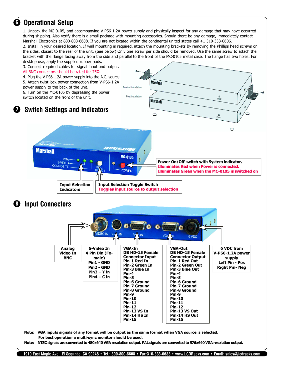
7Switch Settings and Indicators

Power On/Off switch with System indicator.

Illuminates Red when Power is connected.

Illuminates Green when the MC-0105 is switched on

Input Selection

Indicators

78 Input Connectors

Input Selection Toggle Switch

Toggles input source to output selection

Analog

Video In

BNC

S-Video In

4 Pin Din (Fe-

male)

Pin1 - GND

Pin2 - GND

Pin3 – Y in

Pin4 – C in

VGA-In

DB HD-15 Female

Connector Input

Pin-1 Red In

Pin-2 Green In

Pin-3 Blue In

Pin-4

Pin-5

Pin-6 Ground

Pin-7 Ground

Pin-8 Ground

Pin-9

Pin-10

Pin-11

Pin-12

Pin-13 VS In

Pin-14 HS In

Pin-15

VGA-Out

DB HD-15 Female

Connector Output

Pin-1 Red Out

Pin-2 Green Out

Pin-3 Blue Out

Pin-4

Pin-5

Pin-6 Ground

Pin-7 Ground

Pin-8 Ground

Pin-9

Pin-10

Pin-11

Pin-12

Pin-13 VS Out

Pin-14 HS Out

Pin-15

6 VDC from

V-PS6-1.2A power

supply

Left Pin - Pos

Right Pin- Neg

Note: VGA inputs signals of any format will be output as the same format when VGA source is selected. For best operation a multi-sync monitor should be used.

Note: NTSC signals are converted to 480x640 VGA resolution output. PAL signals are converted to 576x640 VGA resolution output.

1910 East Maple Ave. El Segundo, CA 90245 • Tel.: 800-800-6608Fax:310-333-0688 • www.LCDRacks.com • Email: sales@lcdracks.com

Page 2
Image 2
Marshall electronic MC-0105 specifications Operational Setup, Switch Settings and Indicators, Input Connectors