On-Screen Menu (continued)
IMD CONFIGURATION SUBMENU (continued)
■IMD ID #
The IMD ID # identifies each screen to the controlling device. When using the TSL protocol, the ID # of each screen should be manually set in conjunction with the controlling device. When using the Image Video protocol, the ID # may be set automatically by the controlling device, after each IMD is initially identified by IMD Name (see “IMD Name[S/N]” below). Available ID #s are
■IMD Group #
Each screen can be assigned an IMD Group # when using the Marshall protocol. Available Group #s are
■IMD Name (S/N)
Use this setting to assign a name to each screen when using the Image Video or
Press ENTER to edit the IMD Name. Use the and buttons to move the cursor. Press ENTER with the cursor on the character to be changed and use the and buttons to scroll through character options. Press ENTER to choose a character.
■IMD Baud Rate
Use this setting to choose the baud rate. The baud rate must be set in conjunction with the controlling device. Available baud rates are 300, 600, 1200, 2400, 4800, 9600, 19200, 38400, 57600, 115200. The TSL v4.0 protocol is fixed at 38400 bauds.
■IMD Fixed Align
Use this setting to choose the horizontal alignment of the IMD text. IMD text can be justified on the left, center or right of the screen. This setting is overridden when using IMD text via the Image Video protocol (alignment is set via Image Video protocol).
■IMD Fixed Color
Use this setting to choose the color of the IMD Fixed String text (see below). Available colors are red, green, and yellow. This setting does not affect text color when using IMD text via the Image Video or TSL v4.0 protocols (text color is set via the protocols).
■IMD Fixed String
Use this setting to display static IMD text on the screen. This setting is used to enter IMD text locally, when a serial protocol is not used for remote control. The IMD Fixed String is saved after power cycle. The IMD Fixed String will be overridden by serial protocol commands.
Press ENTER to edit the IMD Fixed String. Use the and buttons to move the cursor. Press ENTER with the cursor on the character to be changed and use the and buttons to scroll through character options. Press ENTER to choose a character.
Installation and Initial Setup
■Unpacking
Carefully unpack the
•
•
•Mounting Bracket
•Operating Instructions
Inspect the unit for any physical damage that may have occurred during shipping. Should there be any damage, immediately contact Marshall Electronics at (800)
■Installation
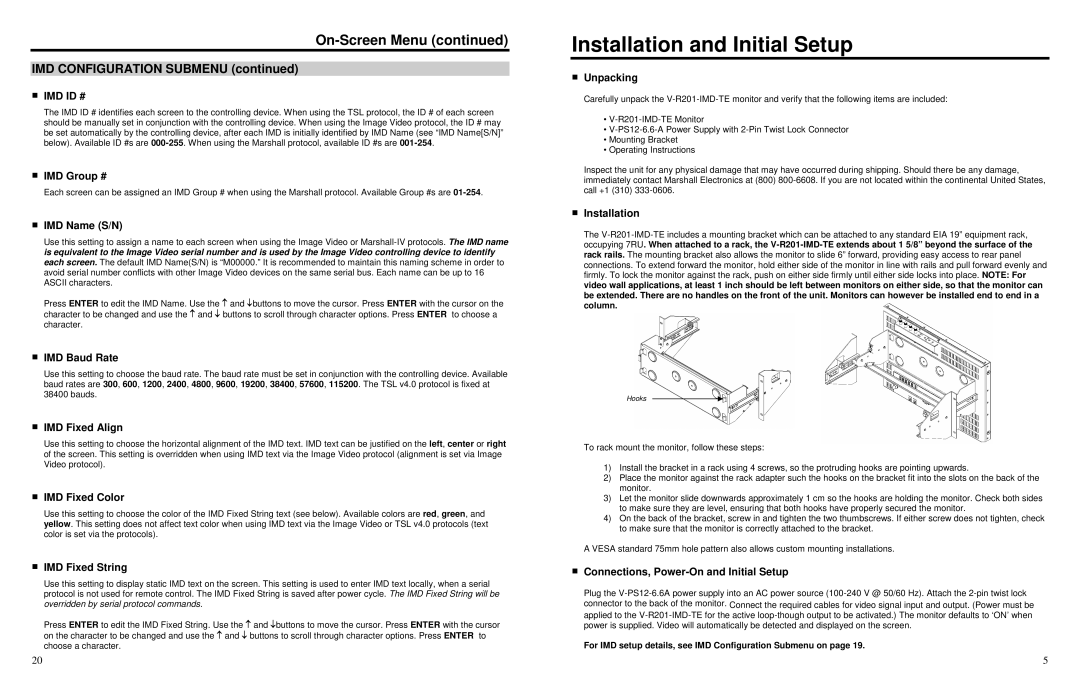
The
Hooks
To rack mount the monitor, follow these steps:
1)Install the bracket in a rack using 4 screws, so the protruding hooks are pointing upwards.
2)Place the monitor against the rack adapter such the hooks on the bracket fit into the slots on the back of the monitor.
3)Let the monitor slide downwards approximately 1 cm so the hooks are holding the monitor. Check both sides to make sure they are level, ensuring that both hooks have properly secured the monitor.
4)On the back of the bracket, screw in and tighten the two thumbscrews. If either screw does not tighten, check to make sure that the monitor is correctly attached to the bracket.
A VESA standard 75mm hole pattern also allows custom mounting installations.
■Connections, Power-On and Initial Setup
Plug the
For IMD setup details, see IMD Configuration Submenu on page 19.
20 | 5 |
