MartinLogan The Quest Speaker System user manual Standard Connection, Bi-WireConnection, position

Models: The Quest Speaker System

1 28
Download 28 pages 16.84 Kb
Page 11
Image 11
Standard Connection

CAUTION!

Turn your amplifier off before making or breaking any signal connections! The chassis is earth grounded and can present a short circuit to your amplifier if contact is made!
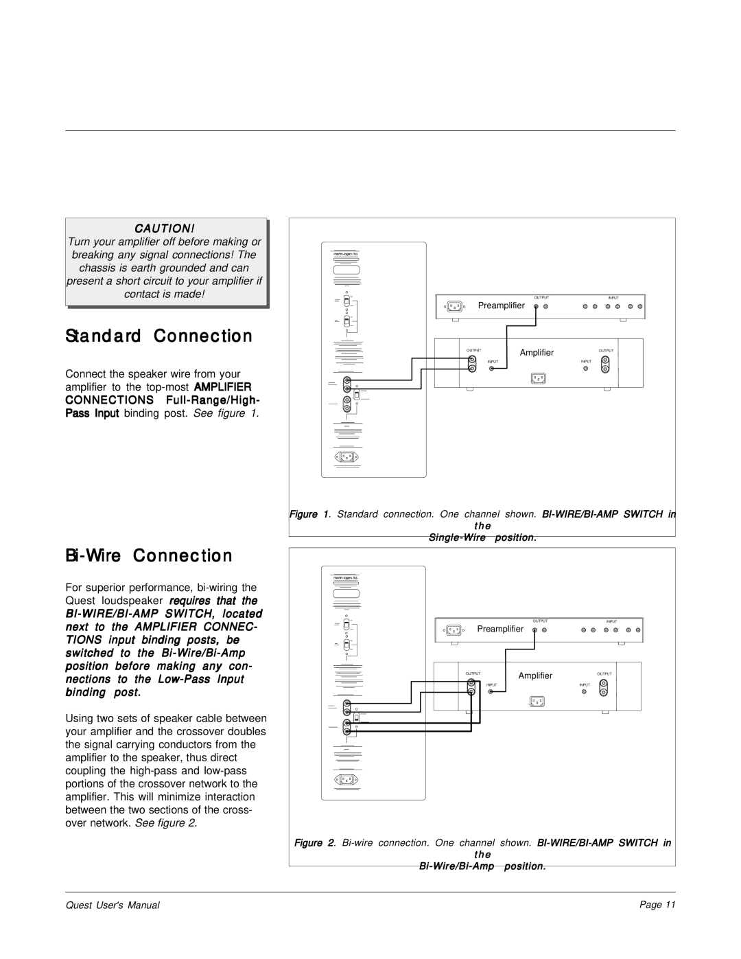
Standard Connection

Connect the speaker wire from your amplifier to the top-most AMPLIFIER

CONNECTIONS Full-Range/High- Pass Input binding post. See figure 1.

Bi-Wire Connection

For superior performance, bi-wiring the Quest loudspeaker requires that the

BI-WIRE/BI-AMP SWITCH, located next to the AMPLIFIER CONNEC- TIONS input binding posts, be switched to the Bi-Wire/Bi-Amp position before making any con- nections to the Low-Pass Input binding post.

Using two sets of speaker cable between your amplifier and the crossover doubles the signal carrying conductors from the amplifier to the speaker, thus direct coupling the high-pass and low-pass portions of the crossover network to the amplifier. This will minimize interaction between the two sections of the cross- over network. See figure 2.


OUTPUT

INPUT

Preamplifier


OUTPUT

Amplifier

OUTPUT


INPUT

INPUT

Figure 1. Standard connection. One channel shown. BI-WIRE/BI-AMP SWITCH in

the


Single-Wire

position.


OUTPUT

INPUT

Preamplifier


OUTPUT

Amplifier

OUTPUT


INPUT

INPUT

Figure 2. Bi-wire connection. One channel shown. BI-WIRE/BI-AMP SWITCH in

the

Bi-Wire/Bi-Amp position.

Quest User's Manual

Page 11

Page 11
Image 11
MartinLogan The Quest Speaker System user manual Standard Connection, Bi-WireConnection, the Bi-Wire/Bi-Ampposition