FULL OVERLAY PANEL INSTALLATION INSTRUCTIONS

Step 5: Drill hinge clearance holes in overlay panel

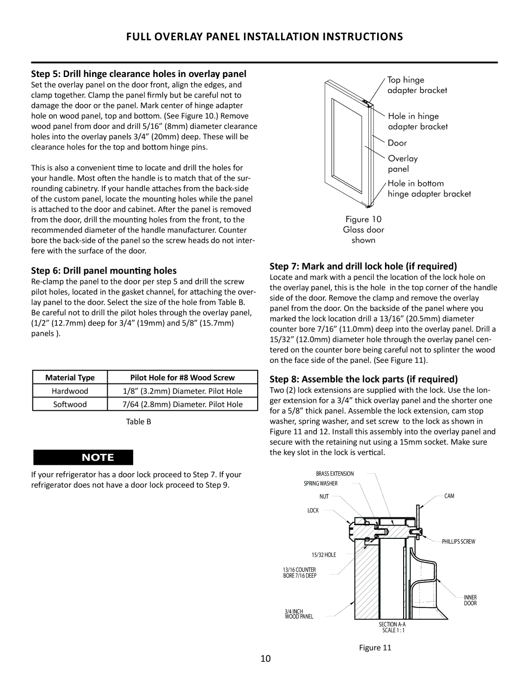
Set the overlay panel on the door front, align the edges, and clamp together. Clamp the panel firmly but be careful not to damage the door or the panel. Mark center of hinge adapter hole on wood panel, top and bottom. (See Figure 10.) Remove wood panel from door and drill 5/16” (8mm) diameter clearance holes into the overlay panels 3/4” (20mm) deep. These will be clearance holes for the top and bottom hinge pins.

This is also a convenient time to locate and drill the holes for your handle. Most often the handle is to match that of the sur- rounding cabinetry. If your handle attaches from the back-side of the custom panel, locate the mounting holes while the panel is attached to the door and cabinet. After the panel is removed from the door, drill the mounting holes from the front, to the recommended diameter of the handle manufacturer. Counter bore the back-side of the panel so the screw heads do not inter- fere with the surface of the door.

Step 6: Drill panel mounting holes

Re-clamp the panel to the door per step 5 and drill the screw pilot holes, located in the gasket channel, for attaching the over- lay panel to the door. Select the size of the hole from Table B. Be careful not to drill the pilot holes through the overlay panel, (1/2” (12.7mm) deep for 3/4” (19mm) and 5/8” (15.7mm) panels ).

Material Type

Pilot Hole for #8 Wood Screw

Hardwood

1/8” (3.2mm) Diameter. Pilot Hole

Softwood

7/64 (2.8mm) Diameter. Pilot Hole


Table B

NOTE

If your refrigerator has a door lock proceed to Step 7. If your refrigerator does not have a door lock proceed to Step 9.

Top hinge adapter bracket

Hole in hinge adapter bracket

Door

Overlay panel

Hole in bottom

hinge adapter bracket

Figure 10

Glass door

shown

Step 7: Mark and drill lock hole (if required)

Locate and mark with a pencil the location of the lock hole on the overlay panel, this is the hole in the top corner of the handle side of the door. Remove the clamp and remove the overlay panel from the door. On the backside of the panel where you marked the lock location drill a 13/16” (20.5mm) diameter counter bore 7/16” (11.0mm) deep into the overlay panel. Drill a 15/32” (12.0mm) diameter hole through the overlay panel cen- tered on the counter bore being careful not to splinter the wood on the face side of the panel. (See Figure 11).

Step 8: Assemble the lock parts (if required)

Two (2) lock extensions are supplied with the lock. Use the lon- ger extension for a 3/4” thick overlay panel and the shorter one for a 5/8” thick panel. Assemble the lock extension, cam stop washer, spring washer, and set screw to the lock as shown in Figure 11 and 12. Install this assembly into the overlay panel and secure with the retaining nut using a 15mm socket. Make sure the key slot in the lock is vertical.

BRASS EXTENSION


SPRING WASHER


NUT

CAM

LOCK


PHILLIPS SCREW

15/32 HOLE


13/16 COUNTER


BORE 7/16 DEEP


INNER


DOOR

3/4 INCH


WOOD PANEL


SECTION A-A


SCALE 1 : 1

Figure 11

10

Page 10
Image 10
Marvel Group 6GARMP manual Drill hinge clearance holes in overlay panel, Drill panel mounting holes

6GARMP, 6GARM specifications

Marvel Group 6GARM and 6GARMP represent the latest advancements in the realm of high-performance specialized technologies, specifically tailored for the modern demands of network communications and data processing. These groups are indicators of a new trend in mobile communication and computing capabilities, designed to overcome the limitations of existing systems while paving the way for future developments.

One of the primary features of the 6GARM and 6GARMP is the integration of advanced artificial intelligence (AI) algorithms. This integration enables predictive maintenance and autonomous decision-making processes, significantly enhancing the efficiency of network management. By analyzing vast amounts of data in real-time, these AI capabilities ensure optimal performance and connectivity, thereby reducing downtime and improving user experiences.

In terms of technologies, 6GARM and 6GARMP leverage cutting-edge materials science to enhance the durability and lightweight characteristics of devices. This includes the use of graphene and other nanomaterials, which not only improve signal strength and range but also facilitate energy-efficient operations. As a result, users can expect longer battery life and reduced energy consumption, crucial features for an increasingly mobile and connected world.

Another characteristic that sets the 6GARM and 6GARMP apart is their compatibility with a wide array of devices and platforms. The architecture is designed to support seamless integration across different applications, from smart home devices to industrial IoT systems. This versatility ensures that users can enjoy a cohesive experience, regardless of the technology they are utilizing.

Moreover, the cognitive networking capabilities of 6GARM and 6GARMP allow for adaptive and self-organizing network operations. This means that the network can dynamically allocate resources based on current demand, optimizing bandwidth and ensuring consistent service quality. With the expected proliferation of connected devices, such a feature is essential in maintaining reliable and efficient communications.

Finally, security is a paramount concern for the 6GARM and 6GARMP frameworks. They incorporate advanced encryption techniques and decentralized security protocols to safeguard user data and ensure privacy. As cyber threats continue to evolve, the emphasis on robust security measures in these technologies is critical in fostering user trust and confidence.

In summary, Marvel Group 6GARM and 6GARMP represent a transformative leap in connectivity and performance, underpinned by AI, advanced materials, versatile compatibility, cognitive networking, and enhanced security. As these technologies continue to develop, they are poised to redefine the landscape of communication and data processing in the digital age.