MAX1402 Evaluation Kit/Evaluation System

switch, along the top-edge of the µC module. Observe the polarity marked on the board.

5)Connect the USBTO232 board to the 68HC16MODULE- DIP module if you have not done so already.

6)The MAX1402 EV kit software should have already been downloaded and installed in the USBTO232 Quick Start.

FILE

DESCRIPTION


INSTALL.EXE

Installs the EV kit files on your computer.


UNINST.INI

Database for uninstall program.


Removes the EV kit files from your

UNMAXIM.EXE

computer. This file is automatically copied


to C:\WINDOWS during installation.


7)Start the MAX1402 program by opening its icon in the Start Programs menu.

8)Turn on power supply and slide SW1 to the ON position on the 68HC16MODULE-DIP module. Press the OK button to automatically connect and download the KIT1402.C16 file to the module.

9)When the software successfully establishes com- munication with the EV kit board, you will see a con- figuration tool and some other windows. Verify that the CLKIN and reference voltage settings are cor- rect. Close or minimize this dialog box.

10)Apply input signals to the inputs labeled AIN1–AIN5, at the bottom-edge of the MAX1402 EV kit board. AIN6 is analog common. Observe the readout on the screen.

Recommended Equipment (RS-232-to-COM Port/PC Connection Option)

Before beginning, the following equipment is needed:

MAX1402 EV system:

MAX1402 EV kit 68HC16MODULE-DIP

A DC power supply that generates +8VDC to +12VDC at 30–50mA

A user-supplied Windows 98/2000/XP computer with an available serial communications port, preferably a 9-pin plug

A serial cable to connect the computer’s serial port to the 68HC16MODULE-DIP

Note: In the following sections, software-related items are identified by bolding. Text in bold refers to items directly from the EV kit software. Text in bold and

underlined refers to items from the Windows 98/2000/XP operating system.

Connections and Setup

1)Visit the Maxim website (www.maxim-ic.com/evkit- software) to download the latest version of the EV kit software. Save the EV kit software to a temporary folder and uncompress the file (if it is a .zip file).

2)Install the MAX1402 EV kit software on your com- puter by running the INSTALL.EXE program. The program files are copied and icons are created for them in the Windows Start Programs menu.

3)Make sure your 68HC16MODULE-DIP module has the Rev. 2.0 ROM. The software will not function with the Rev. 1.0 ROM.

4)Carefully connect the boards by aligning the 40-pin header of the MAX1402 EV kit with the 40-pin con- nector of the 68HC16MODULE-DIP module. Gently press them together. The two boards should be flush against one another.

5)Connect the DC power source to the µC module at terminal block J2, located next to the ON/OFF switch, along the top-edge of the µC module. Observe the polarity marked on the board.

6)Connect a cable from the computer’s serial port to the µC module. If using a 9-pin serial port, use a straight-through, 9-pin female-to-male cable. If the only available serial port uses a 25-pin connector, a standard 25-pin-to-9-pin adapter will be required. The EV kit software checks the modem status lines (CTS, DSR, and DCD) to confirm that the correct port has been selected.

FILE

DESCRIPTION


INSTALL.EXE

Installs the EV kit files on your computer.

UNINST.INI

Database for uninstall program.


Removes the EV kit files from your

UNMAXIM.EXE

computer. This file is automatically copied


to C:\WINDOWS during installation.


7)Start the MAX1402 program by opening its icon in the Start Programs menu.

8)Turn the power on and slide SW1 to the ON posi- tion. Select the correct serial port and press the OK button. The program will automatically download KIT1402.C16 to the module.

9)When the software successfully establishes com- munication with the EV kit board, you will see a con- figuration tool and some other windows. Verify that the CLKIN and reference voltage settings are cor- rect. Close or minimize this dialog box.

Evaluate: MAX1400/MAX1402

_______________________________________________________________________________________ 3

Page 3
Image 3
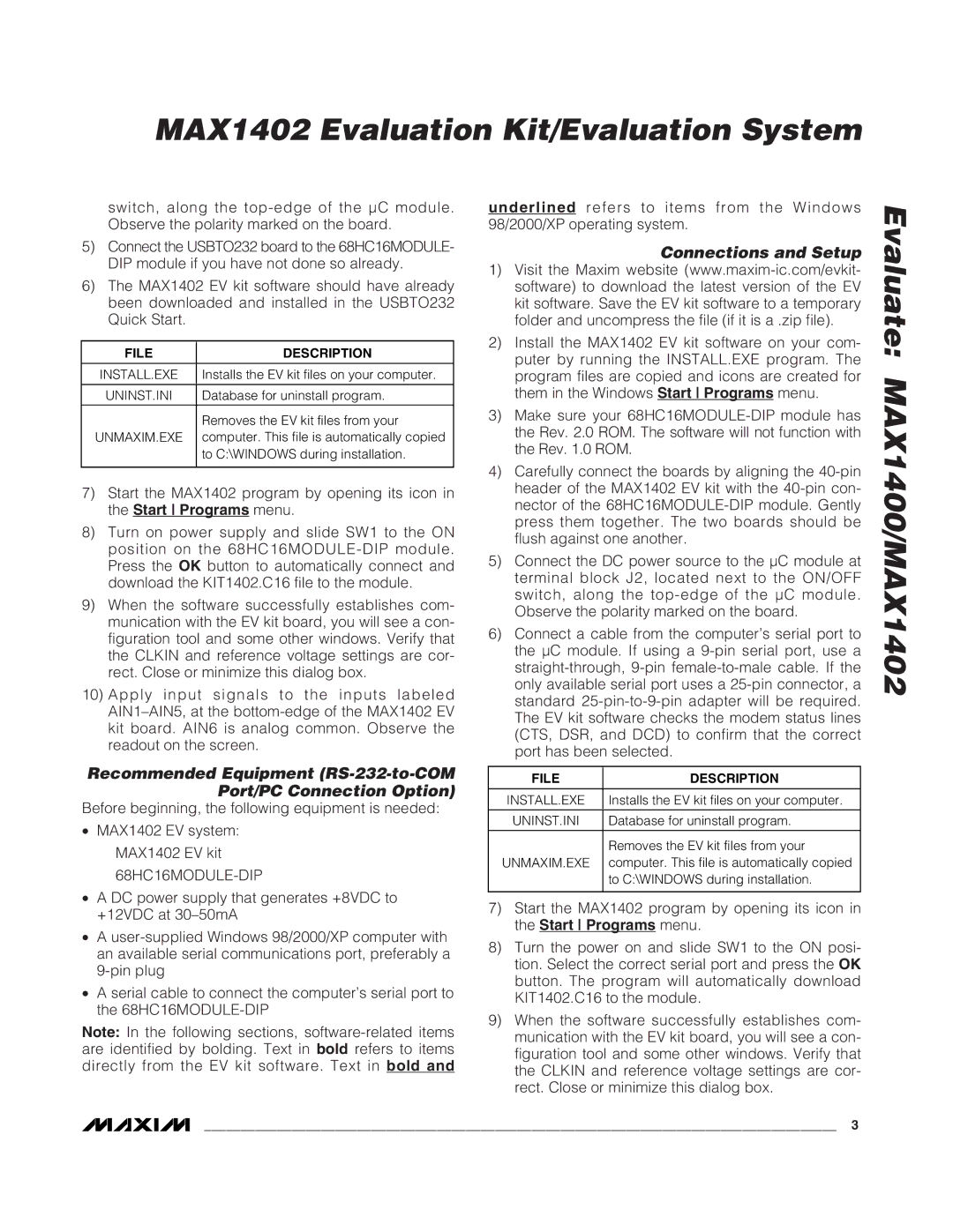
Maxim MAX1402 manual Connections and Setup, Install.Exe, Uninst.Ini, Unmaxim.Exe

MAX1402 specifications

The Maxim MAX1402 is a highly integrated, low-power 12-bit analog-to-digital converter (ADC) that boasts high performance and versatility, making it ideal for a range of applications including industrial control, portable instrumentation, and medical devices. This component incorporates advanced technology aimed at providing accurate and efficient signal processing.

One of the primary features of the MAX1402 is its high resolution of 12 bits, which allows it to effectively convert analog signals into digital data with a level of detail suitable for precision measurements. The device operates at a sampling rate of up to 1 MSPS (million samples per second), allowing it to capture rapid changes in input signals, making it particularly adept for applications requiring real-time data acquisition.

Another notable characteristic is its low power consumption. With a typical operating current of only 500 µA, the MAX1402 is well-suited for battery-operated devices, where energy efficiency is paramount. The low power feature, combined with the ability to run off a single supply voltage, enhances the device's adaptability in various circuit designs.

The MAX1402 features an onboard sample-and-hold circuit, which facilitates effective signal stability during the conversion process. This is crucial in preventing distortion from high-frequency signals and helps in achieving precise measurement results even in noisy environments.

The converter supports a differential input configuration, which improves common-mode rejection and enhances the overall performance in industrial applications where noise and interference are common. Additionally, the MAX1402 includes an internal reference voltage source, simplifying system design by eliminating the need for external components.

The device is also equipped with a serial interface, which allows for straightforward integration with microcontrollers and other digital systems. This feature streamlines the process of data transmission, enabling seamless communication and control within various systems.

With its compact design and robust performance, the MAX1402 addresses the need for accurate, low-power ADCs in modern electronic applications. Its combination of features, such as 12-bit resolution, 1 MSPS sampling rate, low power consumption, and integrated functionality, positions it as a reliable choice for engineers and designers seeking to enhance their measurement and control systems.