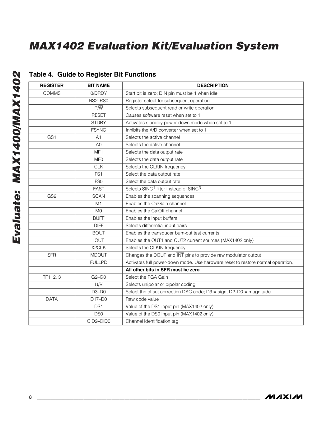
MAX1402 specifications
The Maxim MAX1402 is a highly integrated, low-power 12-bit analog-to-digital converter (ADC) that boasts high performance and versatility, making it ideal for a range of applications including industrial control, portable instrumentation, and medical devices. This component incorporates advanced technology aimed at providing accurate and efficient signal processing.One of the primary features of the MAX1402 is its high resolution of 12 bits, which allows it to effectively convert analog signals into digital data with a level of detail suitable for precision measurements. The device operates at a sampling rate of up to 1 MSPS (million samples per second), allowing it to capture rapid changes in input signals, making it particularly adept for applications requiring real-time data acquisition.
Another notable characteristic is its low power consumption. With a typical operating current of only 500 µA, the MAX1402 is well-suited for battery-operated devices, where energy efficiency is paramount. The low power feature, combined with the ability to run off a single supply voltage, enhances the device's adaptability in various circuit designs.
The MAX1402 features an onboard sample-and-hold circuit, which facilitates effective signal stability during the conversion process. This is crucial in preventing distortion from high-frequency signals and helps in achieving precise measurement results even in noisy environments.
The converter supports a differential input configuration, which improves common-mode rejection and enhances the overall performance in industrial applications where noise and interference are common. Additionally, the MAX1402 includes an internal reference voltage source, simplifying system design by eliminating the need for external components.
The device is also equipped with a serial interface, which allows for straightforward integration with microcontrollers and other digital systems. This feature streamlines the process of data transmission, enabling seamless communication and control within various systems.
With its compact design and robust performance, the MAX1402 addresses the need for accurate, low-power ADCs in modern electronic applications. Its combination of features, such as 12-bit resolution, 1 MSPS sampling rate, low power consumption, and integrated functionality, positions it as a reliable choice for engineers and designers seeking to enhance their measurement and control systems.
