V.34+, K56Plus, 56K BPS specifications
MaxTech 56K BPS, K56Plus, and V.34+ are modem technologies that revolutionized data transmission in the late 1990s, allowing users to connect to the Internet at unprecedented speeds. As internet usage skyrocketed during this period, the need for faster, more efficient modem standards became paramount. MaxTech, a prominent player in the telecommunications industry, was at the forefront of this evolution.One of the standout features of MaxTech 56K modems is their ability to exploit the existing telephone infrastructure for faster data transmission. The 56K BPS technology specifically allowed for download speeds of up to 56 kilobits per second, leveraging a combination of digital signal processing and advanced modulation techniques. This was a significant leap from the earlier 33.6K modems, providing users with enhanced access to online content, file downloads, and multimedia experiences.
K56Plus, another critical technology developed during this era, improved upon the 56K standard by enabling modems to achieve higher speeds in optimal conditions. It utilized both analog and digital transmission paths to maximize throughput, making it more versatile and efficient than its predecessors. This adaptability allowed for better performance in varied line conditions, something essential for comprehensive Internet use.
V.34+, an enhancement of the V.34 modem standard, introduced better error correction and modulation schemes, ensuring more reliable and robust connections. This technology featured improved handling of data corruption and transmission errors, which was vital for maintaining stable internet connectivity during longer sessions, particularly for those downloading large files or streaming audio.
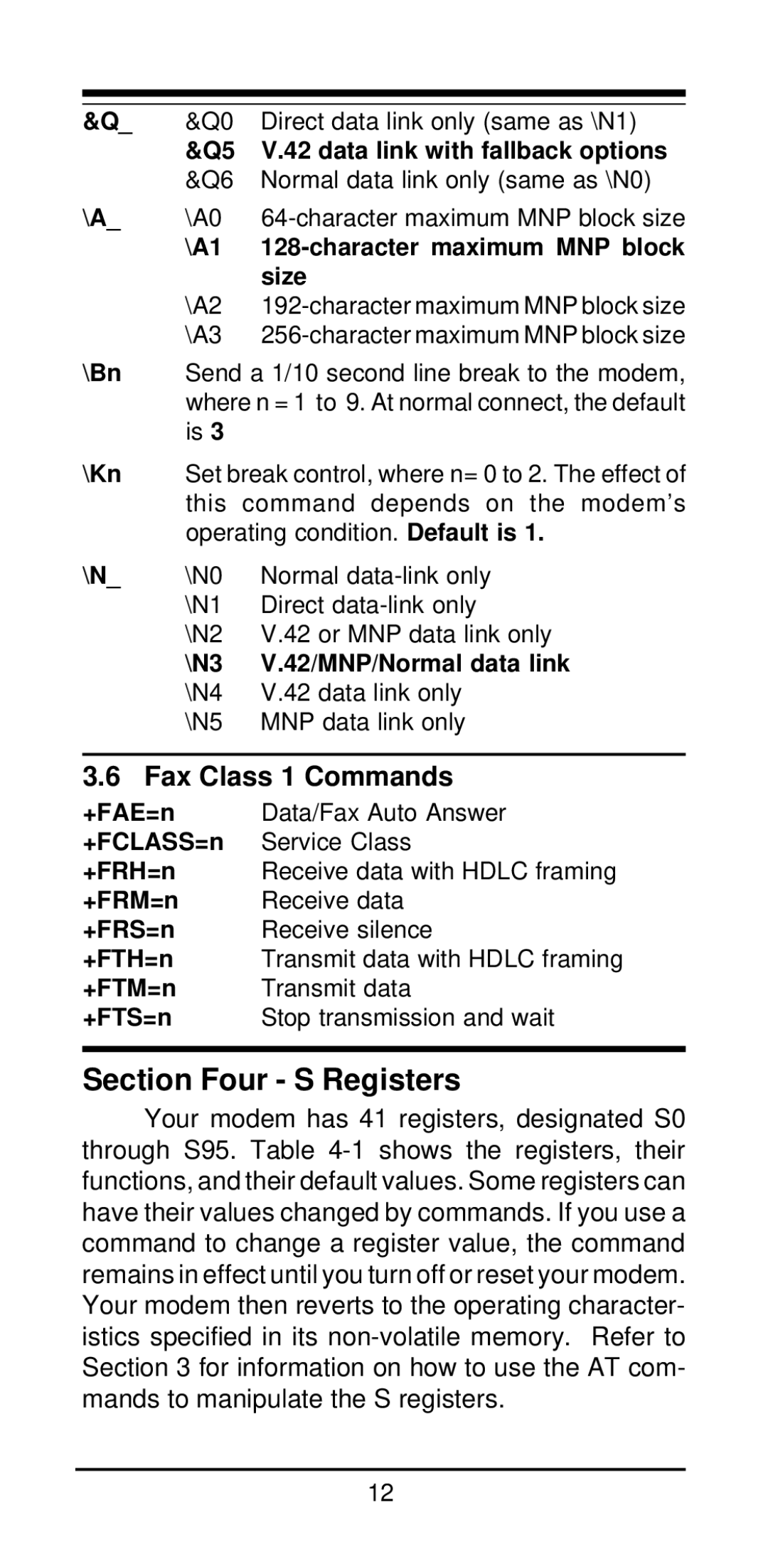
In terms of characteristics, MaxTech modems were known for their user-friendly interfaces and plug-and-play capabilities, making installation a seamless experience for a majority of users. These modems also incorporated technologies such as V.42 error correction and MNP protocol, further enhancing the reliability of data transmission.
Overall, MaxTech 56K BPS, K56Plus, and V.34+ mark a significant chapter in the history of internet connectivity. They provided a foundation for the broadband revolution that followed by pushing the limits of dial-up technology. Their advanced features and robust performance paved the way for an era of enhanced online experiences, shaping the way users interacted with the digital landscape for years to come.

