•Plug the
•Attach the power cord to the monitor and plug it into an AC outlet.
•The monitor is now ready for use.
Section 3 - Monitor Controls and LEDs
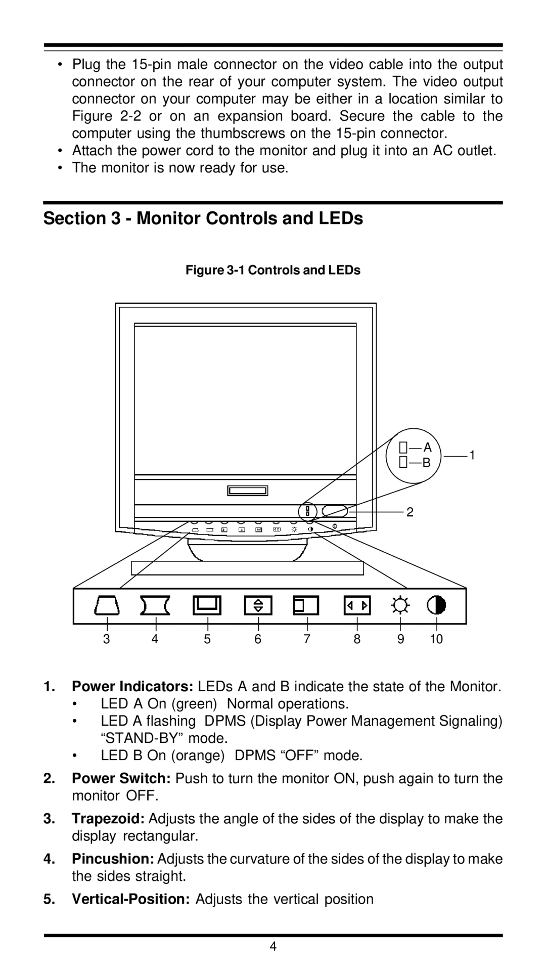
Figure 3-1 Controls and LEDs
A
1
B
2
3 | 4 | 5 | 6 | 7 | 8 | 9 | 10 |
1.Power Indicators: LEDs A and B indicate the state of the Monitor.
•LED A On (green) Normal operations.
•LED A flashing DPMS (Display Power Management Signaling)
•LED B On (orange) DPMS “OFF” mode.
2.Power Switch: Push to turn the monitor ON, push again to turn the monitor OFF.
3.Trapezoid: Adjusts the angle of the sides of the display to make the display rectangular.
4.Pincushion: Adjusts the curvature of the sides of the display to make the sides straight.
5.
4