INSTALLATION
Before installing the drive in the computer, you must determine how the jumpers on the Maxtor hard drive are to be set for your system based upon the use of the Maxtor hard drive as either a Master or Slave device. Maxtor hard drives are shipped with the Master jumper setting enabled.
IMPORTANT: If a Maxtor hard drive is being added to a system on the same cable with an existing IDE device, it may be necessary to
Systems Using Cable Select
IMPORTANT – Most systems do not use this feature. Unless you are sure that your computer system supports Cable Select, do not set up the drive with this feature enabled.
Maxtor hard drives support Cable Select. The Cable Select method of drive identification allows the system to identify Master and Slave IDE devices based upon the position (connector) the IDE device is attached to on the interface (ribbon) cable.
A special IDE cable select interface (ribbon) cable is required for systems using the Cable Select feature.
Systems that use Cable Select do not support the standard Master/Slave definitions described above and the standard IDE interface (ribbon) cable cannot be used on these systems. If your system supports this feature, refer to the system user’s manual or contact the system manufacturer for specific procedures for installing hard drives.
On Maxtor hard drives, Cable Select is enabled by installing a jumper on J48.
Relationship to Other IDE Devices
4 Mounting Drive in System
Turn the computer OFF, disconnect the power cord and remove the cover. Refer to the computer user’s manual for information on removing the cover.
Each system manufacturer uses different types of cases, including desktop,
In a typical system case, there are specific 3.5 inch and 5.25 inch bays available for storage devices. When a 3.5 inch mounting bay is available, mounting brackets are not required. If a 5.25 inch mounting bay is used, mounting brackets will be required to mount the Maxtor hard drive in the system case. Refer to the system manufacturers user’s manual or contact the system manufacturer directly for additional information.
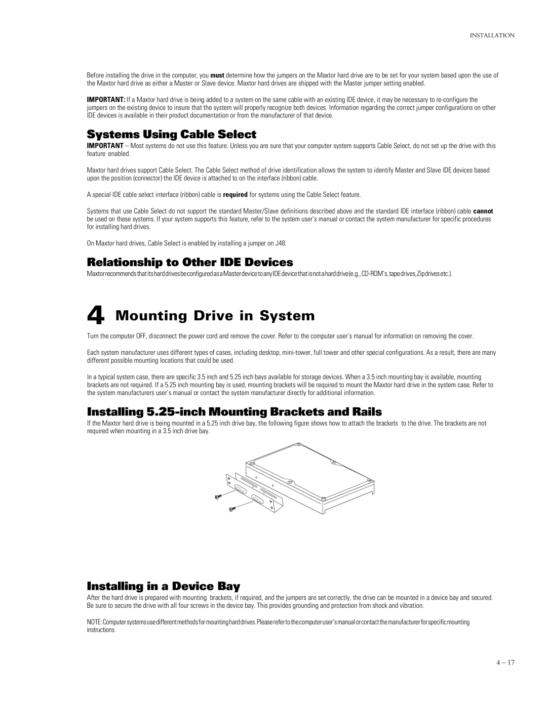
Installing 5.25-inch Mounting Brackets and Rails
If the Maxtor hard drive is being mounted in a 5.25 inch drive bay, the following figure shows how to attach the brackets to the drive. The brackets are not required when mounting in a 3.5 inch drive bay.
Installing in a Device Bay
After the hard drive is prepared with mounting brackets, if required, and the jumpers are set correctly, the drive can be mounted in a device bay and secured. Be sure to secure the drive with all four screws in the device bay. This provides grounding and protection from shock and vibration.
NOTE:Computersystemsusedifferentmethodsformountingharddrives.Pleaserefertothecomputeruser’smanualorcontactthemanufacturerforspecificmounting instructions.
4 – 17