INSTALLATION
2 General Requirements
System Hardware Requirements
The minimum system Maxtor recommends for drives 8.4 GB or less is a 486 DX 66 MHz system. For drives larger than 8.4 GB, we recommend a
BIOS Requirements
System BIOS dated prior to September 1997 do not support drives greater than 8.4 GB. To obtain the full capacity of a drive larger than 8.4 GB, upgrade the BIOS, install a BIOS enhancercardorusetheMaxBlastinstallationsoftware(version9.06ornewer).
Ultra Direct Memory Access (UDMA)
UDMA mode on a Maxtor hard drive will only activate when the drive is installed in a system with full UDMA capability, i.e., a mother board or interface card with the UDMA chips and the associated UDMA software drivers.
OS Requirements for Large Capacity Hard Drives
A full installation of the Windows 95 operating system is required for hard drives larger than 8.4 GB when the drive is a Primary Master. An upgrade to Windows 95 from Windows 3.11 and/or the DOS operating system will not support drive capacities greater than 8.4 GB when the drive is a Primary Master.
3 Hard Drive Identification
IDE stands for Integrated Drive Electronics and EIDE is Enhanced IDE. The IDE or EIDE interface is designed to support two devices – typically hard drives – on a single ribbon cable through one 40 pin connector on the mother board or interface card.
Some mother boards and interface cards may have a second IDE/EIDE connector to support two additional IDE devices. The IDE/EIDE interface is identified as a primary or secondary interface. In systems with only a single connector on the mother board or interface card, it is the primary IDE/EIDE interface. To add a second IDE/EIDE interface requires a special interface card. In systems with two connectors on the mother board or interface card, one is the primary and the other as the secondary.
The primary interface must be used for at least one IDE device before connecting any devices to the secondary IDE interface.
Ribbon cable lengths are limited to 18 inches and have two or three 40 pin connectors. This cable is referred to as a parallel cable and IDE devices may be connected anywhere on the cable. One of the connectors is attached to the IDE connector on the mother board or interface card and the remaining connector(s) are available for the IDE devices.
Identifying IDE Devices on the Interface
Each device must be identified as either the Master or Slave device on that interface (cable). Each cable must have a Master before it can have a Slave device on the cable. There cannot be two Master or two Slave devices on the same cable.
IDE devices use jumpers to designate the Master/Slave identification of the device. Each manufacturer may have its own jumpering scheme to identify the device as a Master or Slave and its relationship to other IDE devices attached to the same cable.
Jumper Settings
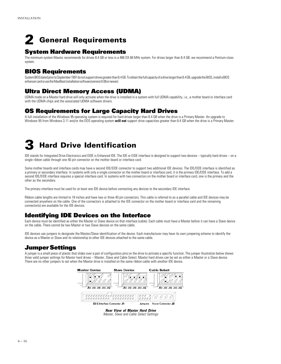
A jumper is a small piece of plastic that slides over a pair of configuration pins on the drive to activate a specific function. The jumper illustration below shows three valid jumper settings for Maxtor hard drives – Master, Slave and Cable Select. Maxtor hard drives can be set as either a Master or a Slave device. There are no other jumpers to set when the Maxtor drive is installed on the same ribbon cable with another IDE device.
Rear View of Maxtor Hard Drive
Master, Slave and Cable Select Settings
4 – 16