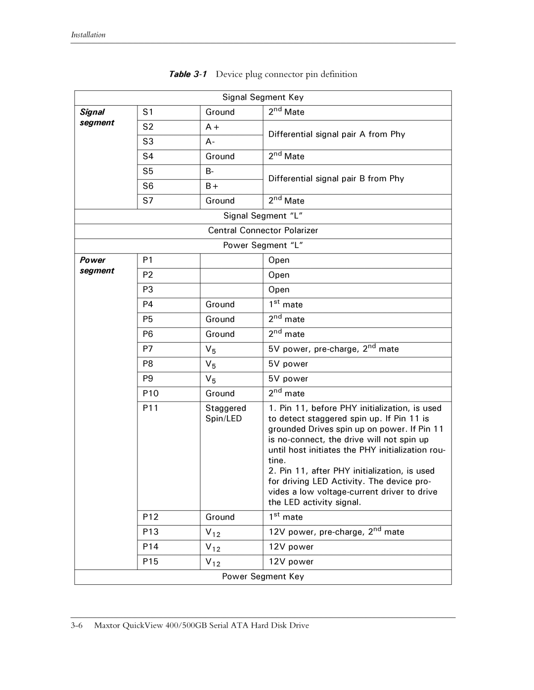
ATA specifications
Maxtor ATA drives have played a significant role in the evolution of data storage technology, particularly during the late 20th and early 21st centuries. Known for their reliability and performance, these drives became a popular choice for consumers and businesses alike.One of the main features of Maxtor ATA (Advanced Technology Attachment) drives is their interface. The ATA standard, which later evolved into the Parallel ATA (PATA) and Serial ATA (SATA) interfaces, allowed for the easy connection of hard drives to computers. This ensured broad compatibility across various systems, making it easier for users to upgrade their storage without facing compatibility issues.
The performance of Maxtor ATA drives was also a notable characteristic. With spinning speeds typically around 5400 RPM and 7200 RPM, these drives provided competitive read and write speeds compared to their contemporaries. The utilization of larger cache memory, often up to 8 MB or more, helped improve data transfer rates, ensuring quick access to files and applications.
Maxtor also deployed various technologies to enhance the reliability and longevity of their drives. One such innovation was the use of Shock Protection technologies, which minimized the risk of data loss due to physical shocks or impacts. This was particularly important for portable storage devices, where movement and jostling are common.
The drives were also designed with data integrity in mind. Maxtor incorporated features like S.M.A.R.T (Self-Monitoring, Analysis, and Reporting Technology) to help predict drive failures by monitoring various parameters. This proactive approach greatly assisted users in taking precautions against data loss.
Capacity-wise, Maxtor ATA drives varied significantly over the years, from a few gigabytes in the early 1990s to several terabytes by the time the brand was phased out. This scalability made Maxtor products suitable for both casual users and enterprises needing to store vast amounts of data.
In conclusion, the Maxtor ATA drives represented a significant step forward in storage technology, combining reliability, performance, and innovation. Their legacy continues to influence modern storage solutions, as many of the underlying principles and technologies have persisted into the current era of data storage. Though the brand is no longer in active development, its impact remains a noteworthy chapter in the history of computing.

