3.4Drive mounting
You can mount the drive in any orientation using four screws in the
•Allow a minimum clearance of 0.030 inches (0.76 mm) around the entire perimeter of the drive for cooling.
•Use only
•The screws should be inserted no more than 0.150 inch (3.81 mm) into the bottom or side mounting holes.
•Do not overtighten the mounting screws (maximum torque: 6
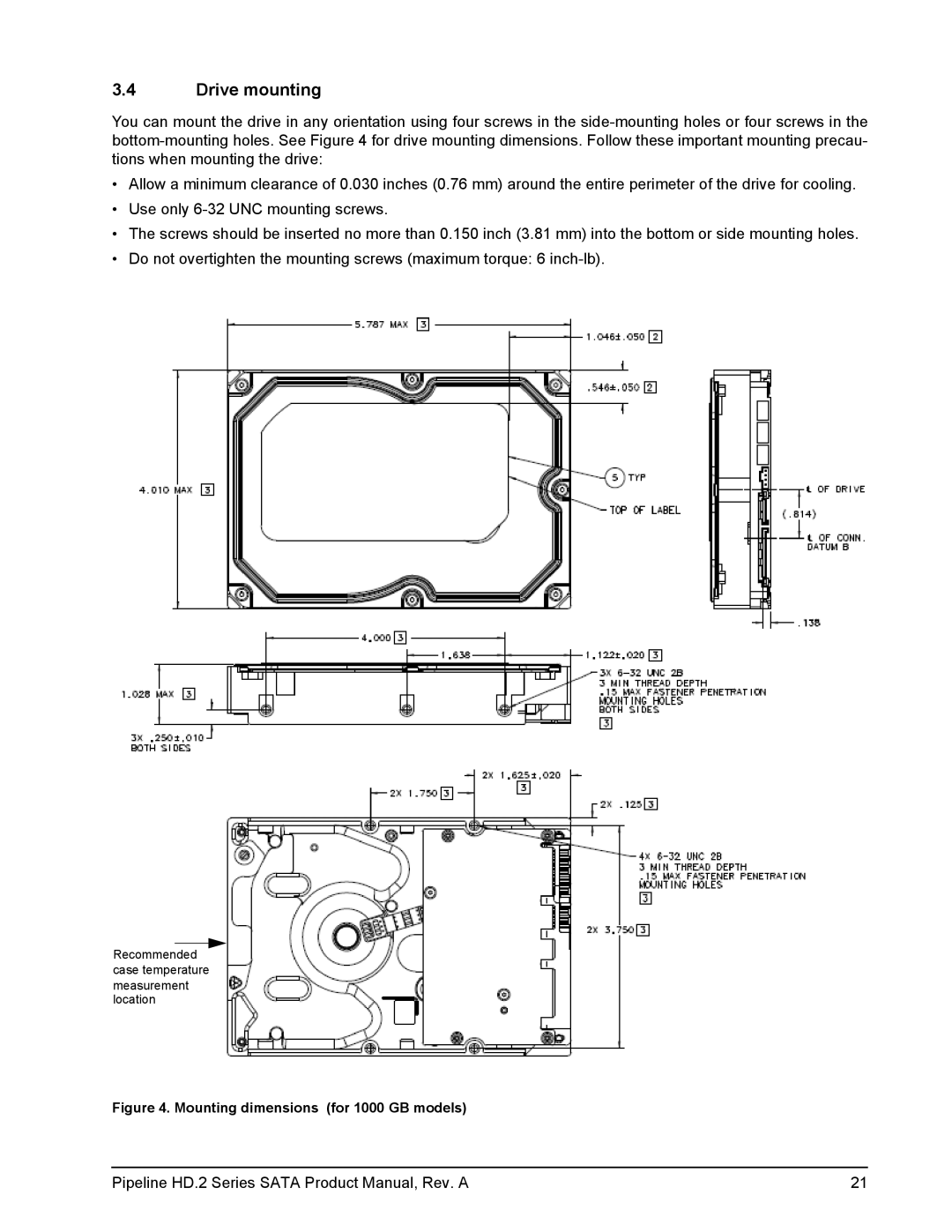
Recommended case temperature
measurement location
Figure 4. Mounting dimensions (for 1000 GB models)
Pipeline HD.2 Series SATA Product Manual, Rev. A | 21 |