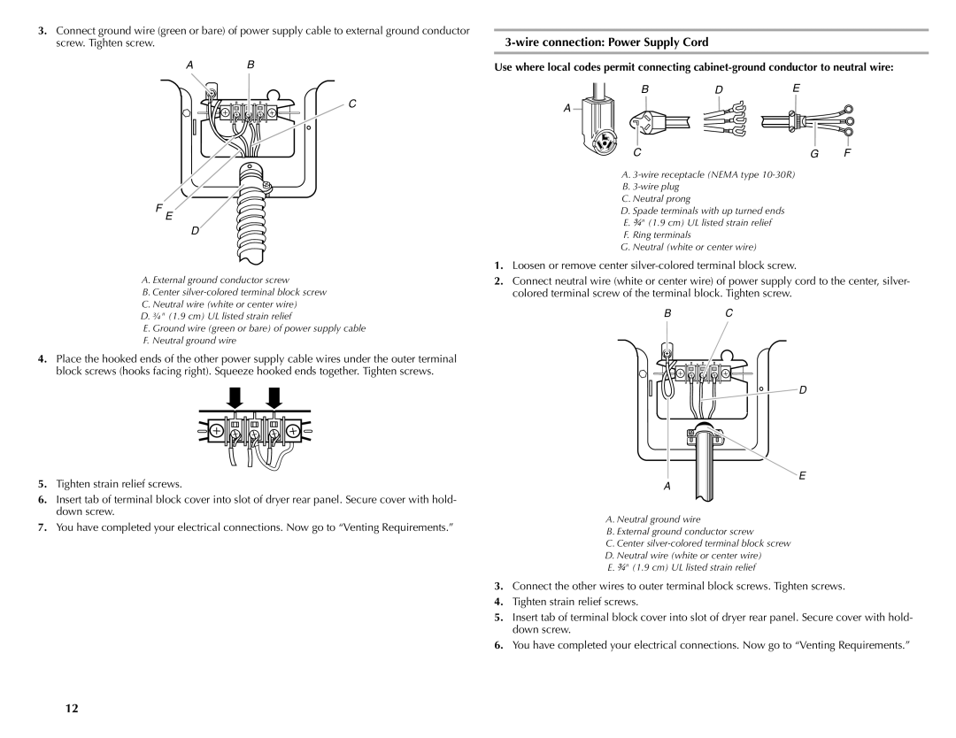
3.Connect ground wire (green or bare) of power supply cable to external ground conductor screw. Tighten screw.
A B
C
F
E
D![]()
A.External ground conductor screw
B.Center
C.Neutral wire (white or center wire)
D.¾" (1.9 cm) UL listed strain relief
E. Ground wire (green or bare) of power supply cable F. Neutral ground wire
4.Place the hooked ends of the other power supply cable wires under the outer terminal block screws (hooks facing right). Squeeze hooked ends together. Tighten screws.
5.Tighten strain relief screws.
6.Insert tab of terminal block cover into slot of dryer rear panel. Secure cover with hold- down screw.
7.You have completed your electrical connections. Now go to “Venting Requirements.”
3-wire connection: Power Supply Cord
Use where local codes permit connecting
BDE
A
CG F
A.
B.
C.Neutral prong
D.Spade terminals with up turned ends E. ³⁄₄" (1.9 cm) UL listed strain relief F. Ring terminals
G.Neutral (white or center wire)
1.Loosen or remove center
2.Connect neutral wire (white or center wire) of power supply cord to the center, silver- colored terminal screw of the terminal block. Tighten screw.
B C
![]() D
D
E
A
A. Neutral ground wire
B. External ground conductor screw
C. Center
D. Neutral wire (white or center wire)
E. ³⁄₄" (1.9 cm) UL listed strain relief
3.Connect the other wires to outer terminal block screws. Tighten screws.
4.Tighten strain relief screws.
5.Insert tab of terminal block cover into slot of dryer rear panel. Secure cover with hold- down screw.
6.You have completed your electrical connections. Now go to “Venting Requirements.”
12