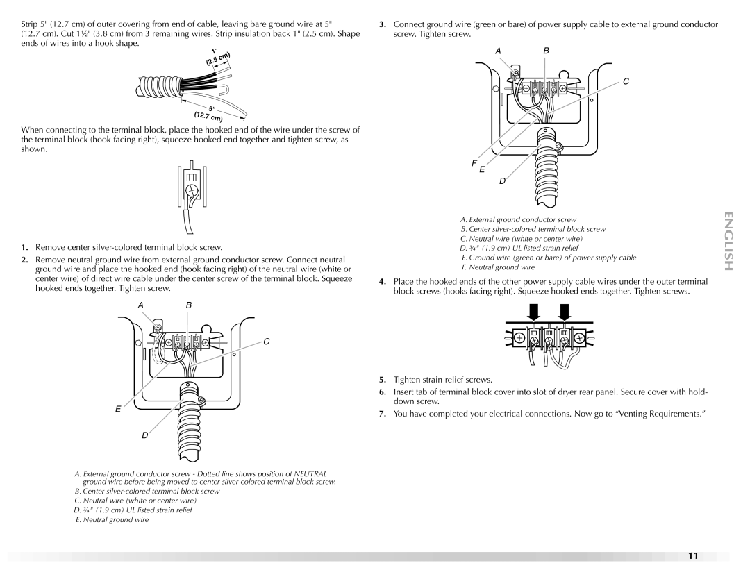
Strip 5" (12.7 cm) of outer covering from end of cable, leaving bare ground wire at 5"
(12.7 cm). Cut 1¹⁄₂" (3.8 cm) from 3 remaining wires. Strip insulation back 1" (2.5 cm). Shape ends of wires into a hook shape.
1" .5cm) (2
5" | |
(12.7 | cm) |
| |
When connecting to the terminal block, place the hooked end of the wire under the screw of the terminal block (hook facing right), squeeze hooked end together and tighten screw, as shown.
1.Remove center
2.Remove neutral ground wire from external ground conductor screw. Connect neutral ground wire and place the hooked end (hook facing right) of the neutral wire (white or center wire) of direct wire cable under the center screw of the terminal block. Squeeze hooked ends together. Tighten screw.
A B
C
E
D
A. External ground conductor screw - Dotted line shows position of NEUTRAL ground wire before being moved to center
B. Center
D. ¾" (1.9 cm) UL listed strain relief E. Neutral ground wire
3.Connect ground wire (green or bare) of power supply cable to external ground conductor screw. Tighten screw.
A B
C
F
E
D![]()
A.External ground conductor screw
B.Center
C.Neutral wire (white or center wire)
D.¾" (1.9 cm) UL listed strain relief
E. Ground wire (green or bare) of power supply cable F. Neutral ground wire
4.Place the hooked ends of the other power supply cable wires under the outer terminal block screws (hooks facing right). Squeeze hooked ends together. Tighten screws.
5.Tighten strain relief screws.
6.Insert tab of terminal block cover into slot of dryer rear panel. Secure cover with hold- down screw.
7.You have completed your electrical connections. Now go to “Venting Requirements.”
11