Table Gib Adjustment
The infeed and outfeed table gibs on your machine are factory adjusted and initially should not require
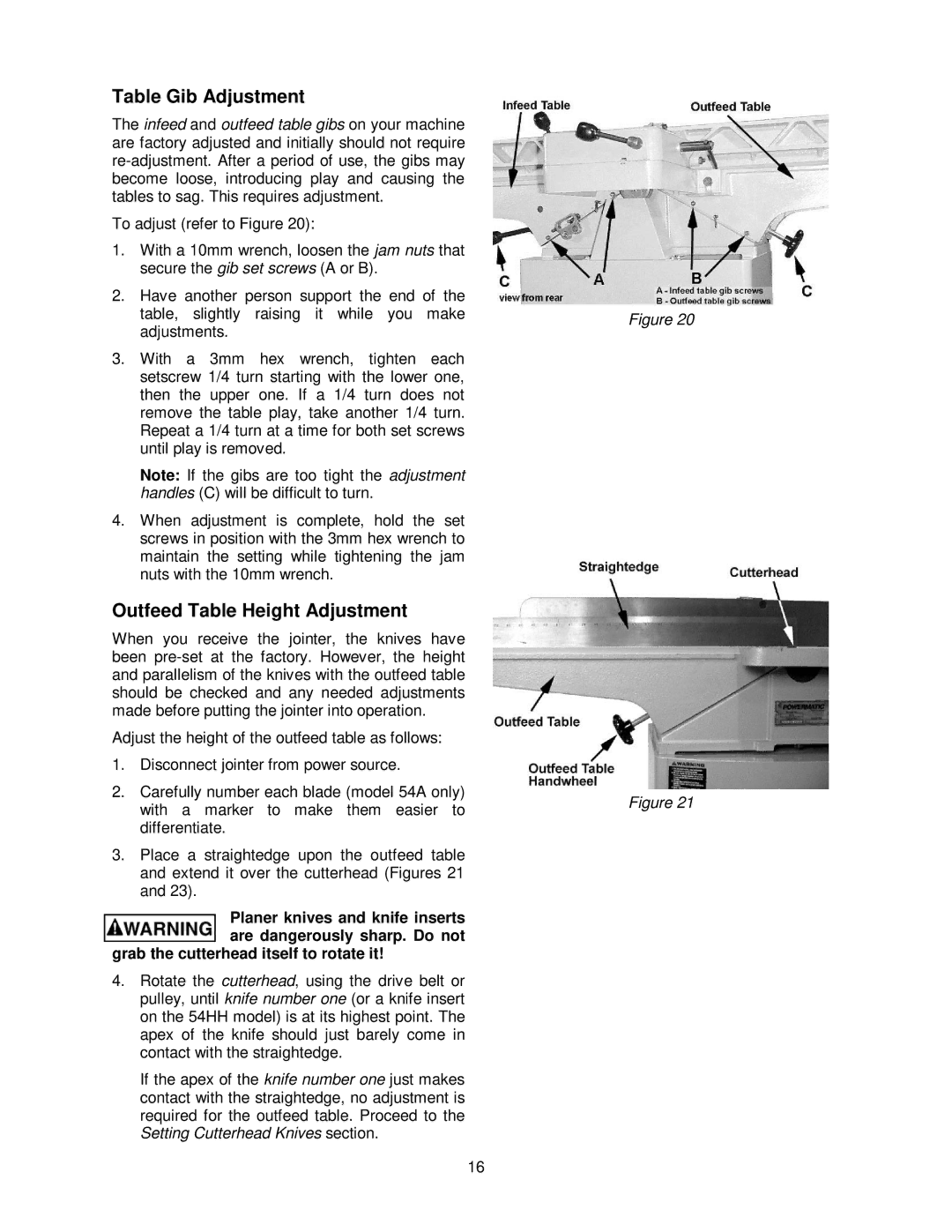
To adjust (refer to Figure 20):
1.With a 10mm wrench, loosen the jam nuts that secure the gib set screws (A or B).
2.Have another person support the end of the table, slightly raising it while you make adjustments.
3.With a 3mm hex wrench, tighten each setscrew 1/4 turn starting with the lower one, then the upper one. If a 1/4 turn does not remove the table play, take another 1/4 turn. Repeat a 1/4 turn at a time for both set screws until play is removed.
Note: If the gibs are too tight the adjustment handles (C) will be difficult to turn.
4.When adjustment is complete, hold the set screws in position with the 3mm hex wrench to maintain the setting while tightening the jam nuts with the 10mm wrench.
Outfeed Table Height Adjustment
When you receive the jointer, the knives have been
Adjust the height of the outfeed table as follows:
1.Disconnect jointer from power source.
2.Carefully number each blade (model 54A only) with a marker to make them easier to differentiate.
3.Place a straightedge upon the outfeed table and extend it over the cutterhead (Figures 21 and 23).
Planer knives and knife inserts are dangerously sharp. Do not
grab the cutterhead itself to rotate it!
4.Rotate the cutterhead, using the drive belt or pulley, until knife number one (or a knife insert on the 54HH model) is at its highest point. The apex of the knife should just barely come in contact with the straightedge.
If the apex of the knife number one just makes contact with the straightedge, no adjustment is required for the outfeed table. Proceed to the Setting Cutterhead Knives section.
16
Figure 20
Figure 21
