STip contact in some cases may cause a light- ning fast reverse REACTION, kicking the
guide bar up and back toward the operator.
SPinching the saw chain along the top of the
guide bar may push the guide bar rapidly back toward the operator.
SEither of these reactions may cause you to lose control of the saw which could result in serious injury. Do not rely exclusively upon the safety devices built into your saw.
CHAIN BRAKE
SChain brake, designed to stop the chain in the event of kickback.
![]() WARNING: Your chain saw is equipped with a chain brake that is designed to stop the chain immediately if you get a kickback. The chain brake reduces the risk of accidents, but only you can prevent them.
WARNING: Your chain saw is equipped with a chain brake that is designed to stop the chain immediately if you get a kickback. The chain brake reduces the risk of accidents, but only you can prevent them.
DO NOT ASSUME THAT THE CHAIN BRAKE WILL PROTECT YOU IN THE EVENT OF A KICKBACK.
SAFETY NOTICE: Exposure to
vibrations through prolonged use of gasoline powered hand tools could cause blood vessel or nerve damage in the fingers, hands, and joints of people prone to circulation disorders or abnormal swellings. Prolonged use in cold weather has been linked to blood vessel damage in otherwise healthy people. If symptoms occur such as numbness, pain, loss of strength, change in skin color or texture, or loss of feeling in the fingers, hands, or joints, discontinue the use of this tool and seek medical attention. An
ASSEMBLY
![]() WARNING: Recheck each assem- bly step if the saw is received assembled. Protective gloves (not provided) should be worn during assembly. Always wear gloves when handling the chain. The chain is sharp and can cut you even when it is not moving!
WARNING: Recheck each assem- bly step if the saw is received assembled. Protective gloves (not provided) should be worn during assembly. Always wear gloves when handling the chain. The chain is sharp and can cut you even when it is not moving!
ATTACHING THE BUMPER SPIKE
The bumper spike may be used as a pivot when making a cut.
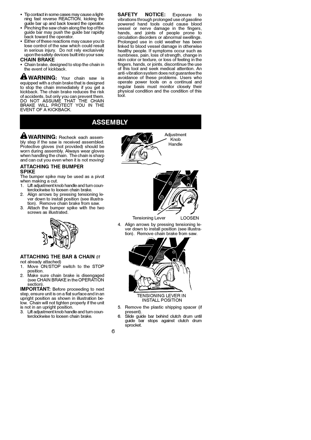
1.Lift adjustment knob handle and turn coun- terclockwise to loosen chain brake.
2.Align arrows by pressing tensioning le- ver down to install position (see illustra- tion). Remove chain brake from saw.
3.Attach the bumper spike with the two screws as illustrated.
Adjustment
Knob
Handle
Tensioning Lever |
| LOOSEN |
4.Align arrows by pressing tensioning le- ver down to install position (see illustra- tion). Remove chain brake from saw.
ATTACHING THE BAR & CHAIN (If
not already attached)
1.Move ON/STOP switch to the STOP position.
2.Make sure chain brake is disengaged (see CHAIN BRAKE in the OPERATION section).
IMPORTANT: Before proceeding to next step, ensure unit is on a flat surface and in an upright position as shown in illustration be- low. Chain will not tighten properly if the unit is not in an upright position.
3.Lift adjustment knob handle and turn coun- terclockwise to loosen chain brake.
TENSIONING LEVER IN
INSTALL POSITION
5.Remove the plastic shipping spacer (if present).
6.Slide guide bar behind clutch drum until guide bar stops against clutch drum sprocket.
6