M85 specifications
The McIntosh M85 is a high-performance audio amplifier that signifies the brand's legendary commitment to excellence in sound reproduction. Known for its robust build quality and sophisticated technology, the M85 exemplifies McIntosh’s pursuit of delivering the finest audio experience to both audiophiles and casual listeners.At the heart of the M85 is its powerful output stage, capable of delivering up to 85 watts per channel with astonishing clarity. This solid-state amplifier employs a unique McIntosh Autoformer technology, which allows it to deliver full power across a wide range of speaker impedances. This means whether you're using 2, 4, or 8-ohm speakers, the M85 can provide consistent power and performance without compromising audio quality.
The M85 is designed with versatility in mind. It features a dual-zone output, allowing the amplifier to simultaneously drive two different speaker sets in separate locations. This is particularly useful for those who want to create multi-room audio solutions or enjoy a different sonic experience in various areas of their home.
One of the standout features of the M85 is its use of McIntosh’s renowned Power Guard technology. This system actively monitors the output signal and protects the amplifier against clipping, ensuring that your music maintains its integrity at high volumes. This technology not only safeguards the amplifier itself but also protects your speakers from potential damage caused by distortion.
Additionally, the M85 is equipped with Sentry Monitor, another McIntosh hallmark, which detects and responds to dangerous levels of current. This advanced protection circuitry ensures that the amplifier operates safely, even during the most demanding listening sessions.
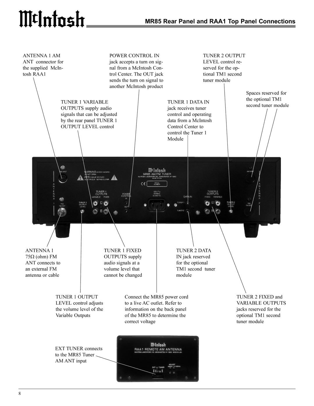
The M85 also includes numerous connectivity options such as balanced and unbalanced inputs, making it easy to integrate into any existing audio setup. The amplifier features a sleek design, complete with the classic McIntosh blue watt meters, which provide visual feedback of the amplifier’s performance.
In summary, the McIntosh M85 amplifier represents a perfect blend of power, technology, and aesthetic elegance. Its advanced features ensure that every note is reproduced with the utmost fidelity, making it a top choice for audio enthusiasts who demand the best from their sound systems. Whether you're listening to music for leisure or critical evaluation, the M85 promises a listening experience that is both powerful and refined.

