Manuals
/
McIntosh
/
Home Audio
/
Stereo Amplifier
McIntosh
MA7000
owner manual
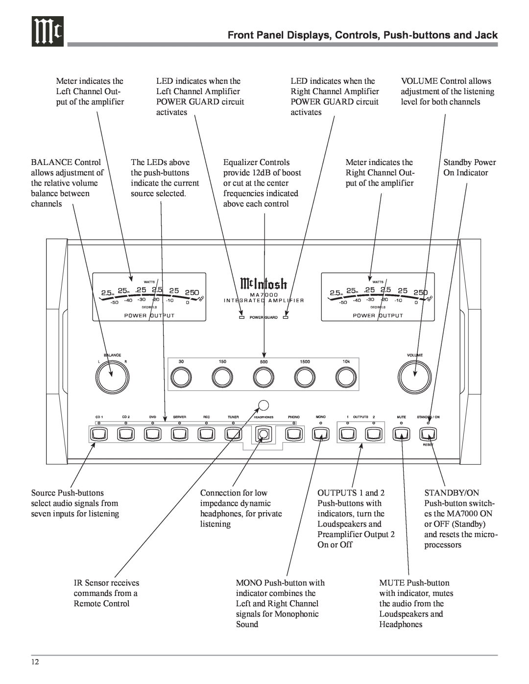
Meter indicates the
Models:
MA7000
1
12
20
20
Download
20 pages
7.57 Kb
9
10
11
12
13
14
15
16
Specification
Install
Connecting Components
Dimension
Reset of Microprocessors
Remote Control Push-Buttons
How to
Safety
Power Supply Circuits
Performance Features
Page 12
Image 12
Page 11
Page 13
Page 12
Image 12
Page 11
Page 13
Contents
Integrated Amplifier
IMPORTANT SAFETY INSTRUCTIONS
Customer Service
Table of Contents
Thank You
Please Take A Moment
Connector and Cable Information
Performance Features
Introduction
Dimensions Dimensions
17-1/2
Front View of the MA7000
Rear View of the MA7000
Installation
Installation
Rear Panel Connections
Connecting Components
Power Control Connections
AC Power Cords Connections
Data Control Connections
How to Connect
Connecting Loudspeakers
Remote Control Push-Buttons
How to use the Remote Control
How to use the Remote Control
Meter indicates the
How to Operate the MA7000
How to Operate the MA7000
How to Operate the MA7000, con’t
How to Operate the MA7000, con’t
Using a Separate Power Amplifier
Using Output
Technical Description
Technical Description
Preamplifier Design Philosophy
Power Amplifier Design Philosophy
Power Supply Circuits
Technical Description, con’t
Autoformers
Protection Circuits
Specifications Specifications
Packing Instructions
Packing Instructions
McIntosh Laboratory, Inc 2 Chambers Street
Binghamton, NY
McIntosh Part No
Top
Page
Image
Contents