How to Connect for a Seven Channel System
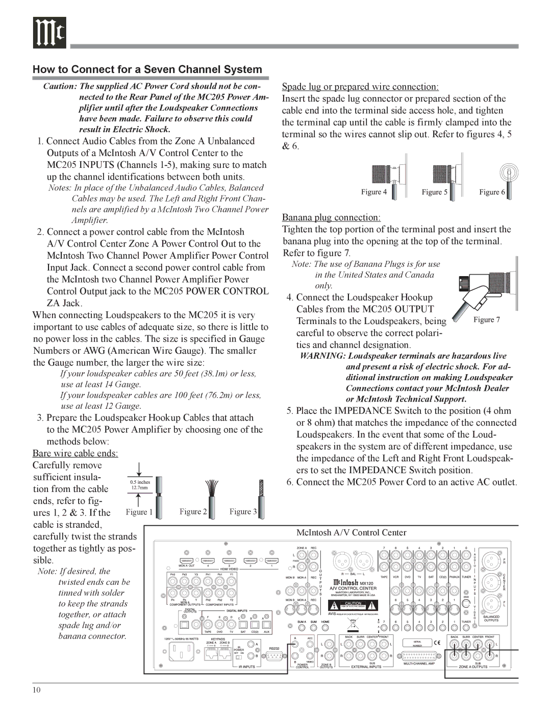
Caution: The supplied AC Power Cord should not be con- | Spade lug or prepared wire connection: | ||||
nected to the Rear Panel of the MC205 Power Am- | Insert the spade lug connector or prepared section of the | ||||
plifier until after the Loudspeaker Connections | cable end into the terminal side access hole, and tighten | ||||
have been made. Failure to observe this could | the terminal cap until the cable is firmly clamped into the | ||||
result in Electric Shock. |
|
| |||
|
| terminal so the wires cannot slip out. Refer to figures 4, 5 | |||
1. Connect Audio Cables from the Zone A Unbalanced | |||||
& 6. | |||||
Outputs of a McIntosh A/V Control Center to the | |||||
| |||||
MC205 INPUTS (Channels |
| ||||
up the channel identifications between both units. |
| ||||
Notes: In place of the Unbalanced Audio Cables, Balanced |
| ||||
Cables may be used. The Left and Right Front Chan- |
| ||||
nels are amplified by a McIntosh Two Channel Power | Banana plug connection: | ||||
Amplifier. |
|
|
| ||
2. Connect a power control cable from the McIntosh | Tighten the top portion of the terminal post and insert the | ||||
A/V Control Center Zone A Power Control Out to the | banana plug into the opening at the top of the terminal. | ||||
McIntosh Two Channel Power Amplifier Power Control | Refer to figure 7. | ||||
Input Jack. Connect a second power control cable from | Note: The use of Banana Plugs is for use | ||||
the McIntosh two Channel Power Amplifier Power | in the United States and Canada | ||||
only. | |||||
Control Output jack to the MC205 POWER CONTROL | |||||
4. Connect the Loudspeaker Hookup | |||||
ZA Jack. |
|
|
| ||
|
|
| Cables from the MC205 OUTPUT | ||
When connecting Loudspeakers to the MC205 it is very | |||||
Terminals to the Loudspeakers, being | |||||
important to use cables of adequate size, so there is little to | |||||
careful to observe the correct polari- | |||||
no power loss in the cables. The size is specified in Gauge | |||||
ties and channel designation. | |||||
Numbers or AWG (American Wire Gauge). The smaller | |||||
WARNING: Loudspeaker terminals are hazardous live | |||||
the Gauge number, the larger the wire size: |
| ||||
| and present a risk of electric shock. For ad- | ||||
If your loudspeaker cables are 50 feet (38.1m) or less, | |||||
ditional instruction on making Loudspeaker | |||||
use at least 14 Gauge. |
|
| |||
|
| Connections contact your McIntosh Dealer | |||
If your loudspeaker cables are 100 feet (76.2m) or less, | |||||
or McIntosh Technical Support. | |||||
use at least 12 Gauge. |
|
| |||
|
| 5. Place the IMPEDANCE Switch to the position (4 ohm | |||
3. Prepare the Loudspeaker Hookup Cables that attach | |||||
or 8 ohm) that matches the impedance of the connected | |||||
to the MC205 Power Amplifier by choosing one of the | |||||
Loudspeakers. In the event that some of the Loud- | |||||
methods below: |
|
|
| ||
|
|
| speakers in the system are of different impedance, use | ||
Bare wire cable ends: |
|
|
| ||
|
|
| the impedance of the Left and Right Front Loudspeak- | ||
Carefully remove |
|
|
| ||
|
|
| ers to set the IMPEDANCE Switch position. | ||
sufficient insula- |
|
|
| ||
|
|
| 6. Connect the MC205 Power Cord to an active AC outlet. | ||
tion from the cable |
|
|
| ||
|
|
|
| ||
ends, refer to fig- |
|
|
|
| |
ures 1, 2 & 3. If the | Figure 1 | Figure 2 | Figure 3 |
| |
cable is stranded, |
|
|
| McIntosh A/V Control Center | |
carefully twist the strands |
|
| |||
|
|
| |||
together as tightly as pos- |
|
|
| ||
sible. |
|
|
|
| |
Note: If desired, the twisted ends can be tinned with solder to keep the strands together, or attach spade lug and/or banana connector.
10